Making a Splay-legged Stool: Part I
I wanted something quick and simple this time. Something that looks pleasing, well-made but doesn't take more than a few hours in the workshop to make as a frame. I made my frame in two hours and spent another hour defining and refining the legs by shaving and shaping. The stool needed to be less tippable than a stool without splay. This one works.
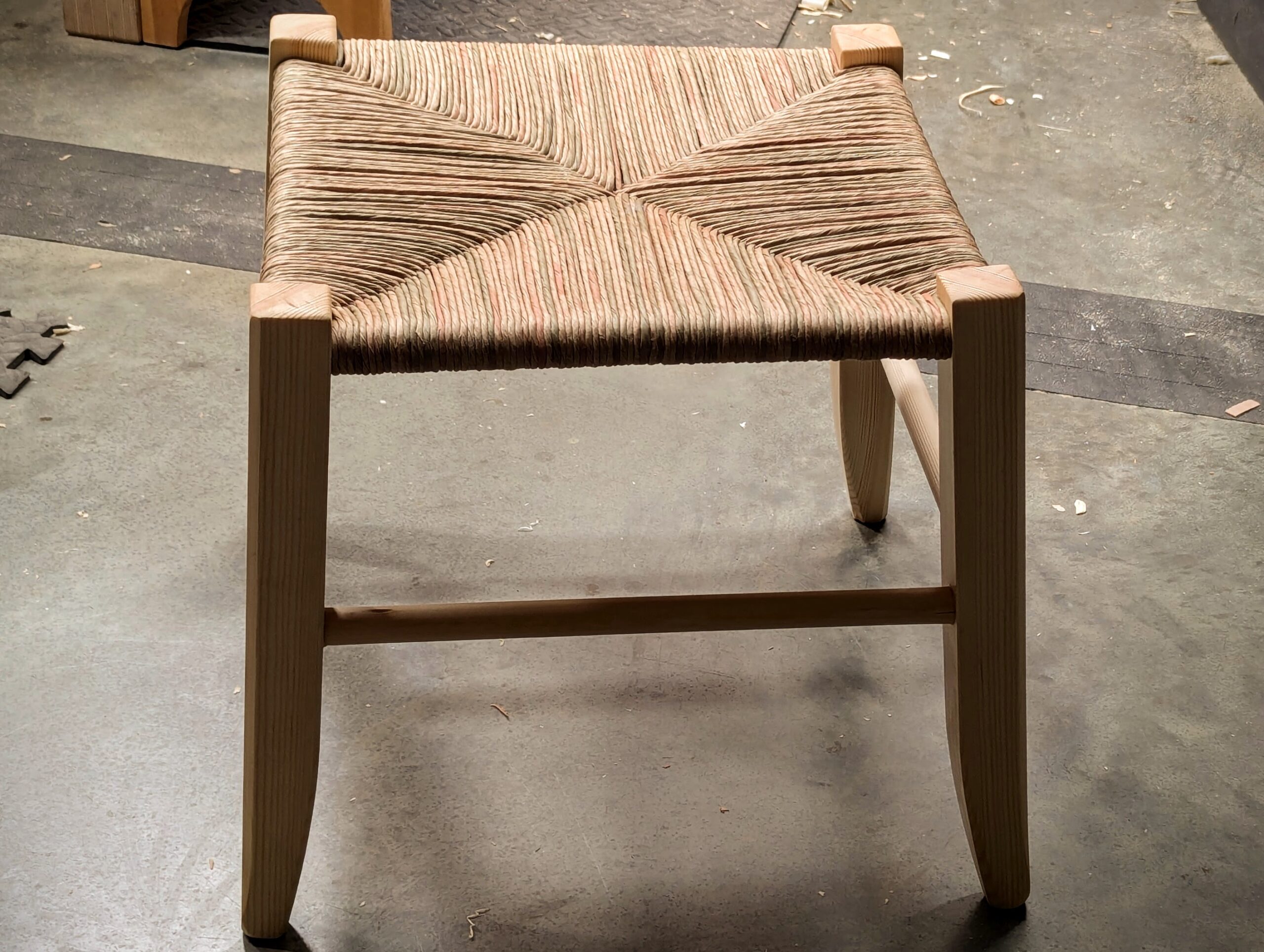
I used 7/8" (22mm) brush stales (broom handles) for the rails, they were less expensive than buying dowels, about a third the price and then a short length of an English four-by-two which measures 3 3/4" by 1 3/4" so ripped down the flat way I got two legs from a width.
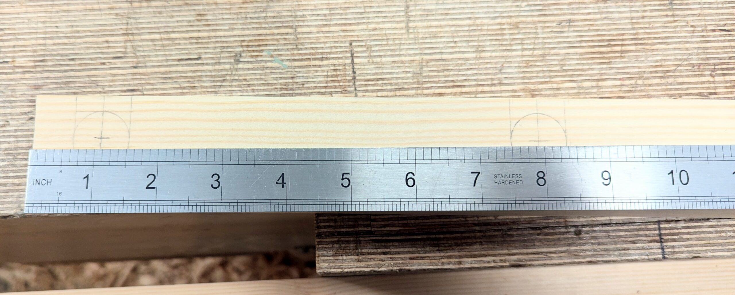
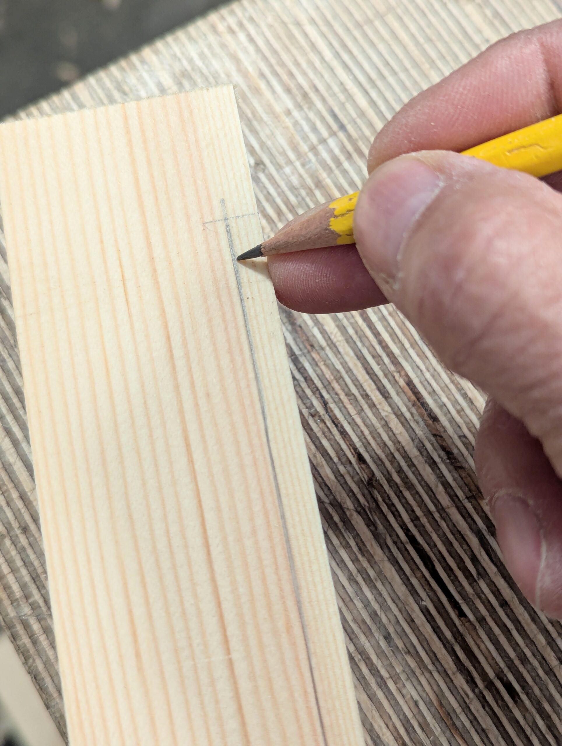
I cut and planed my legs to size, paired them up for looks, and then laid out for two frames to create two frames only. The holes receiving the rails will be quarter of an inch in from the outside face of the legs, so that makes the centre point of the hole 11/16". The top holes start 5/8" from the end of the leg, so this hole's centre point will be 1 1/16" from the top end of the leg.
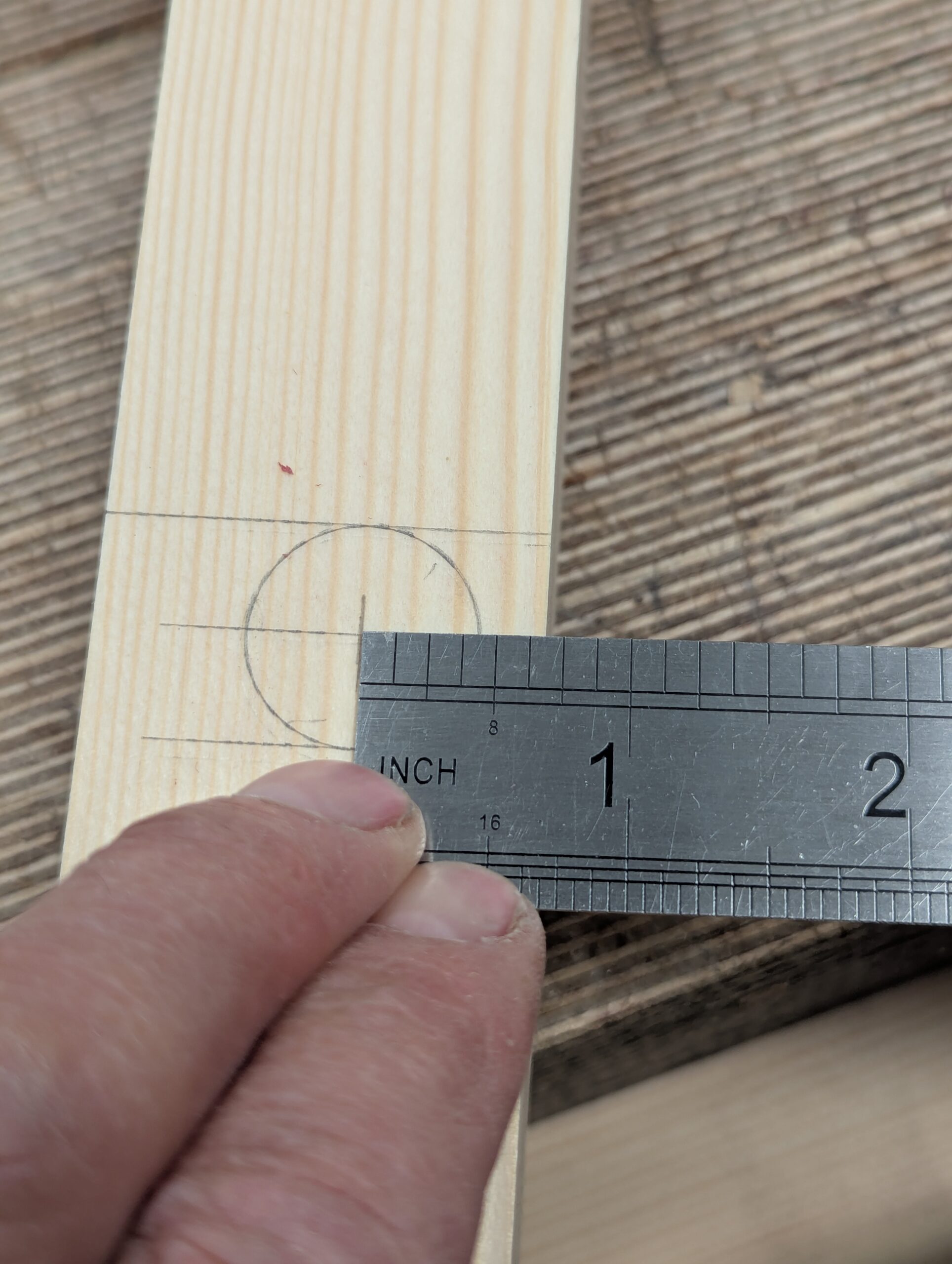
The parallel lower rails will be six inches apart, so the lower centre point will measure 6 7/8"centre to centre and the same distance in from the outside face as the top rail. I suggest that you forget drilling the adjacent holes until you have two opposing frames made and glued up. There's good reason for this; the adjacent rails will partially bore into the first frames and rails. This gives a solid seating to the ends of the added rails for pounding the rails and wedges into later.
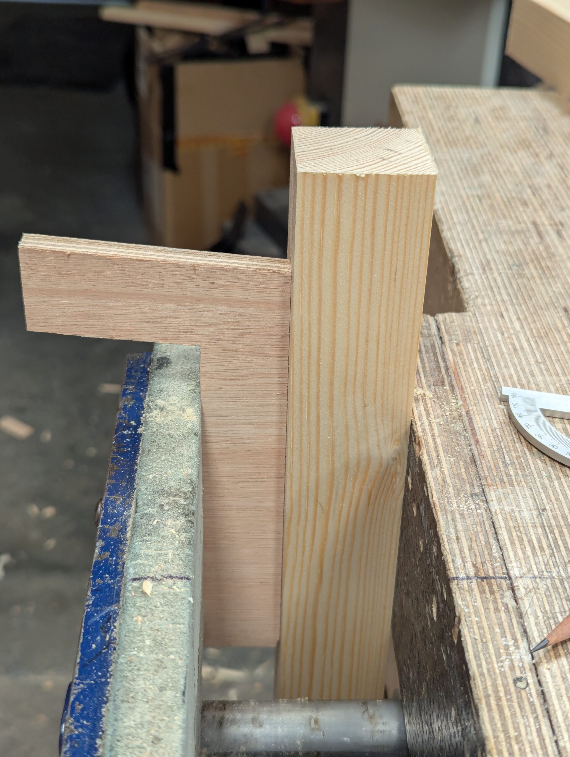
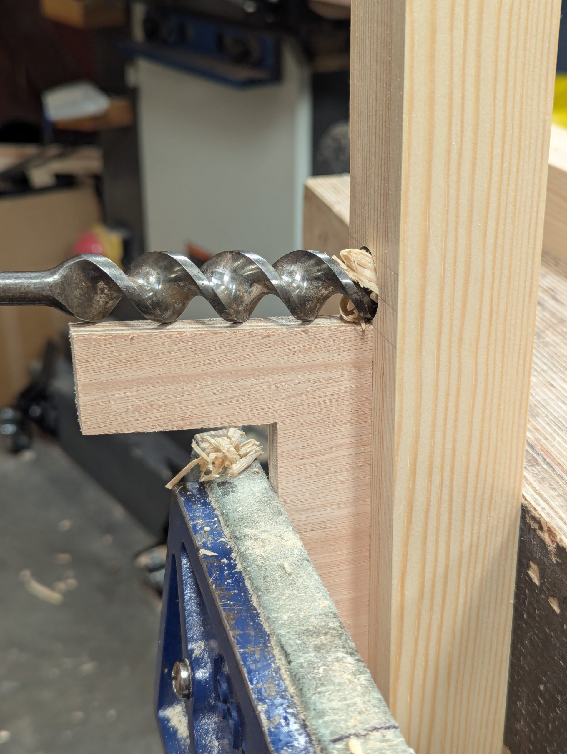
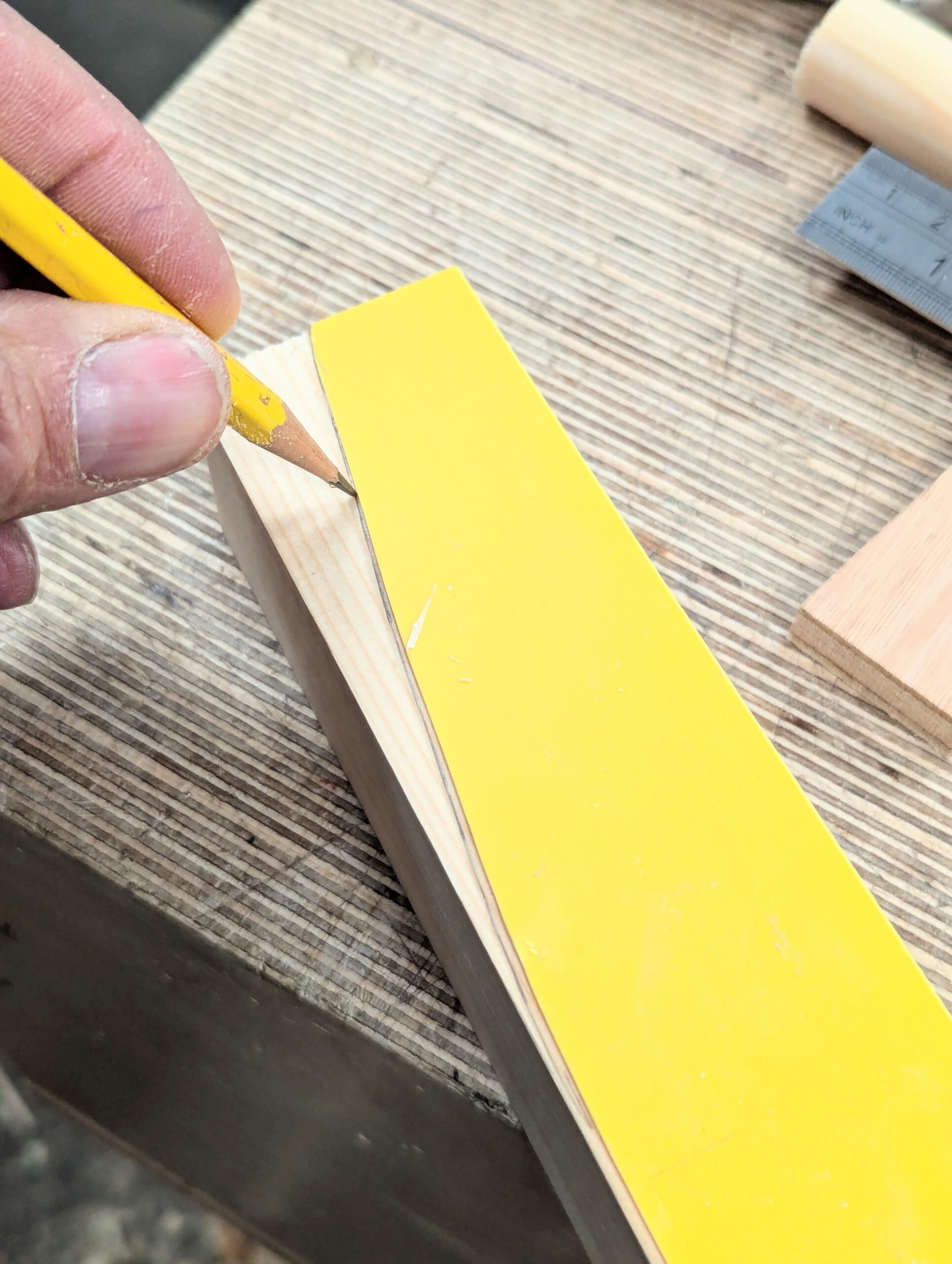
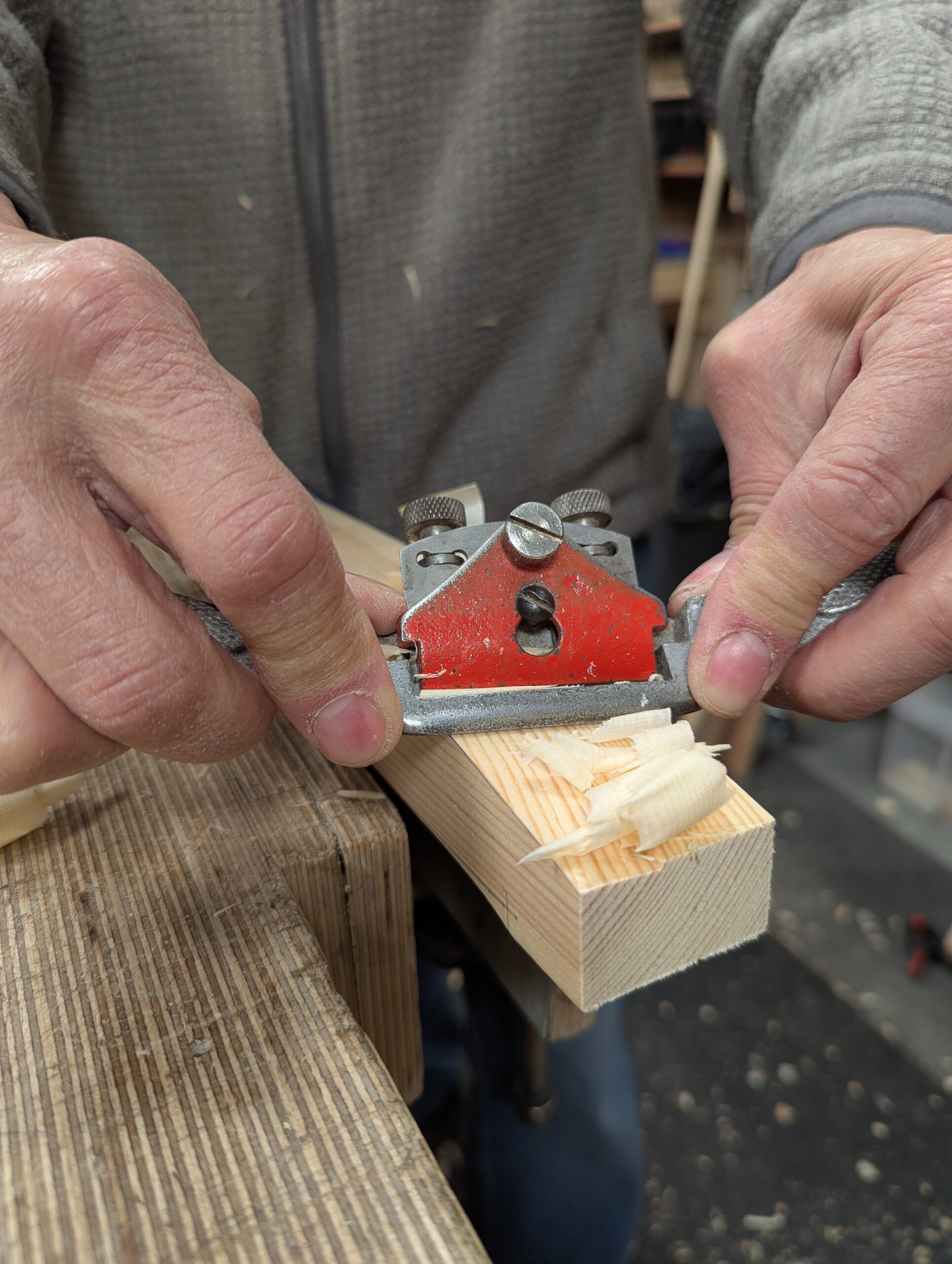
Because the rails and legs create a trapezoidal frame, the rails must favour the angle quite accurately. I set a sliding bevel to 95º and used some half-inch plywood to make my guide from. You can use solid wood, but it won't be as strong.
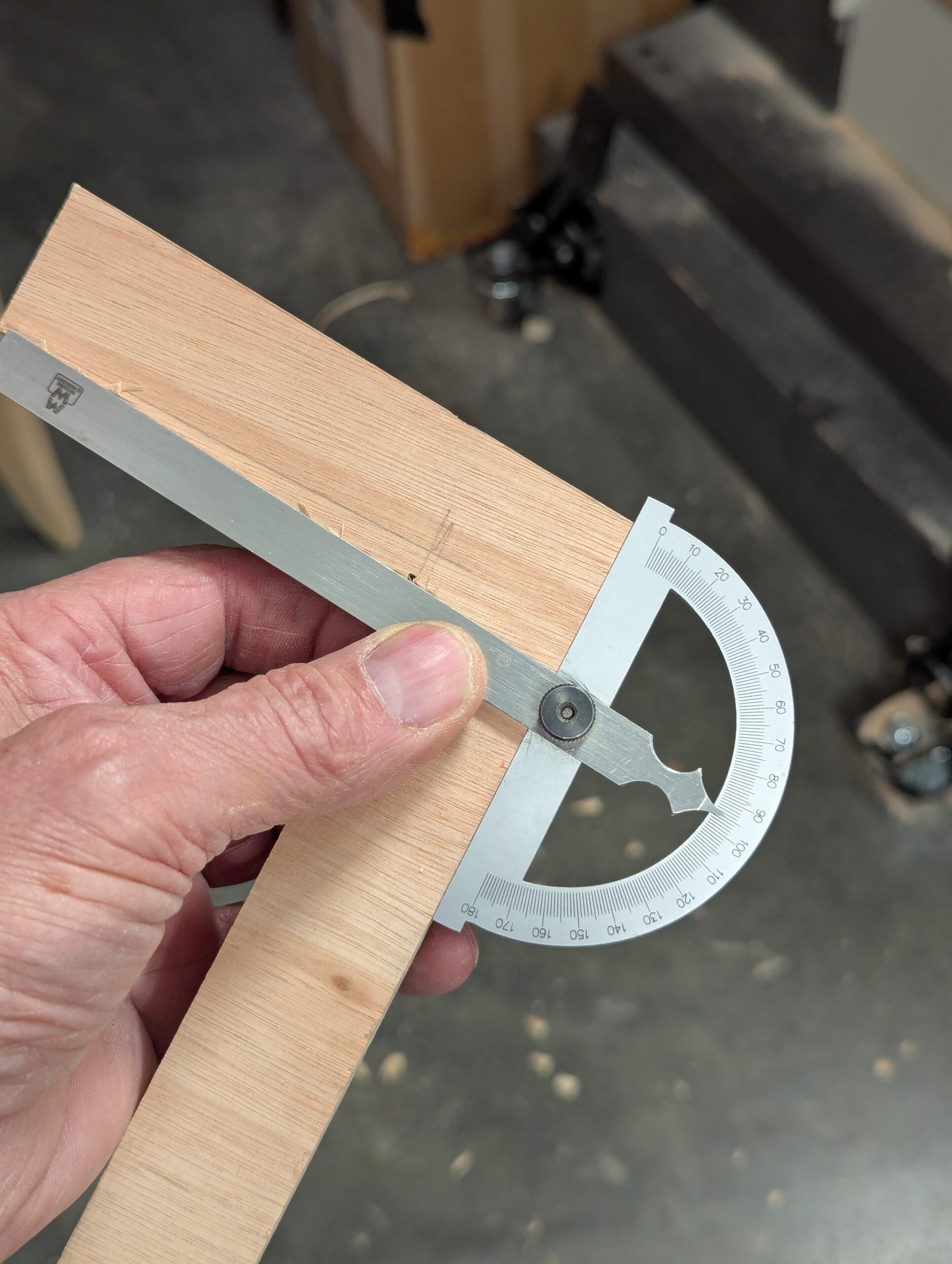
My 'L' measures 5" by 6". Create the angle first by sawing and planing, and then use a gauge to run parallel lines 1" in from the two edges. Cut and trim these cuts as squarely as possible so that when you clamp it to the legs they seat well and allow the clamps to clamp without tilting the guide or the clamps, etc.
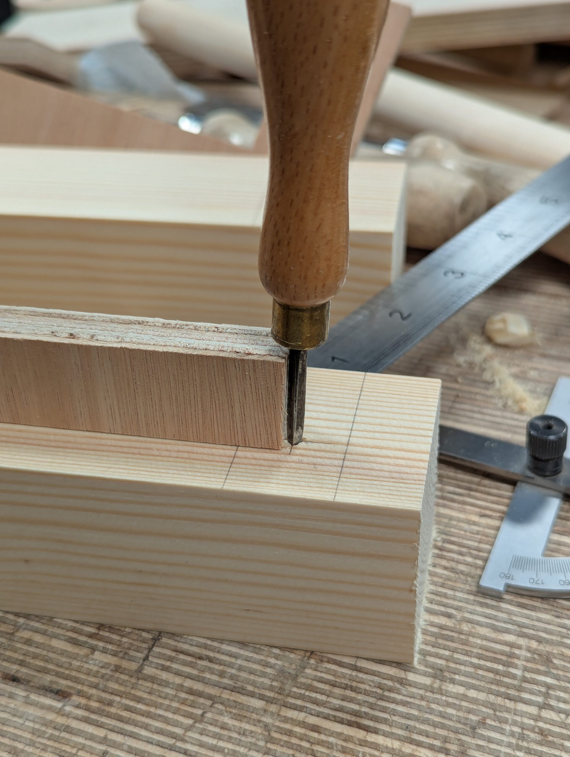
I preferred to start the holes with my awl.
Below, you can see how the guide anchors securely to the legs ready for boring. I used half-inch plywood, and it feels steady and secure.
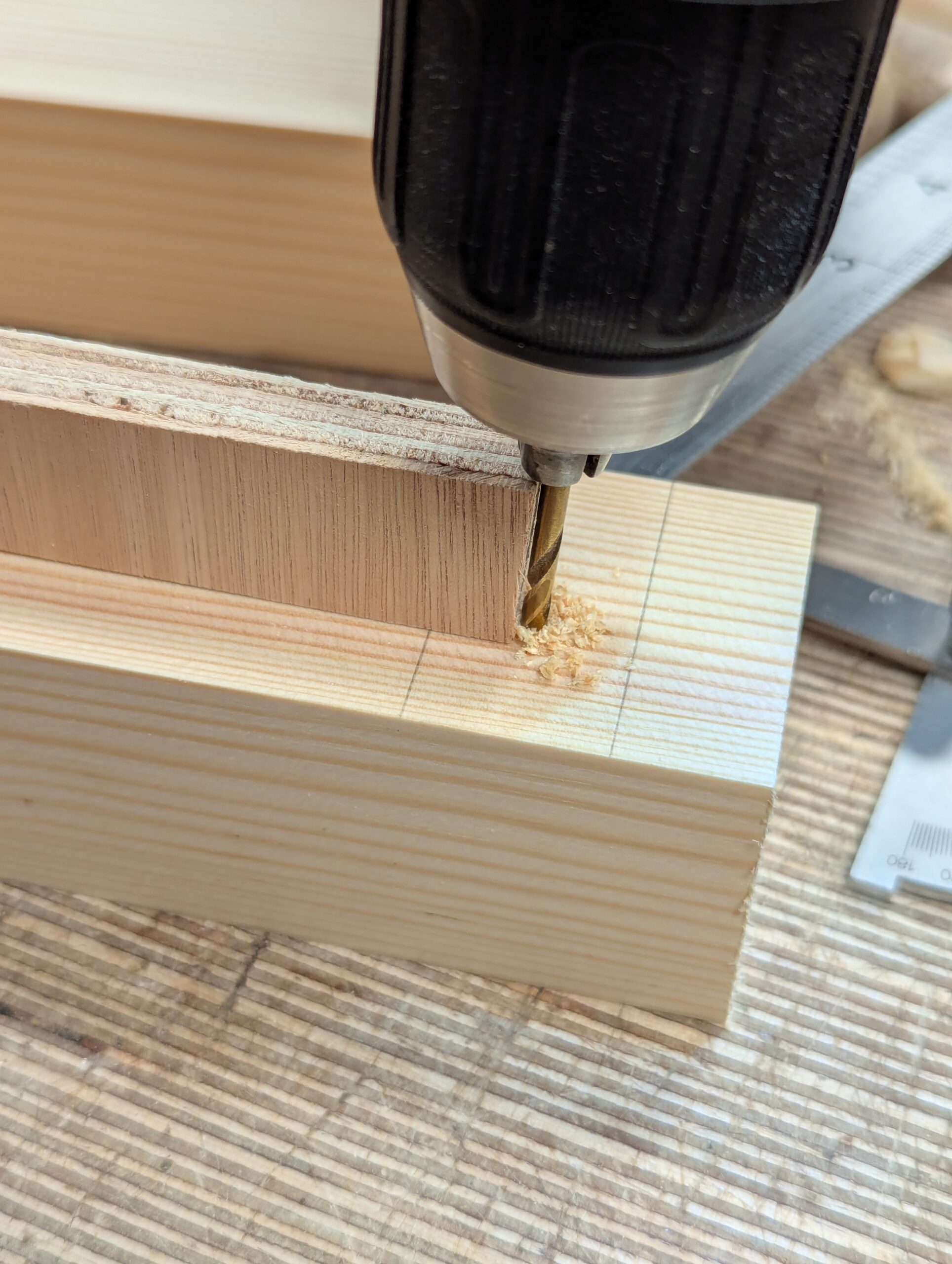
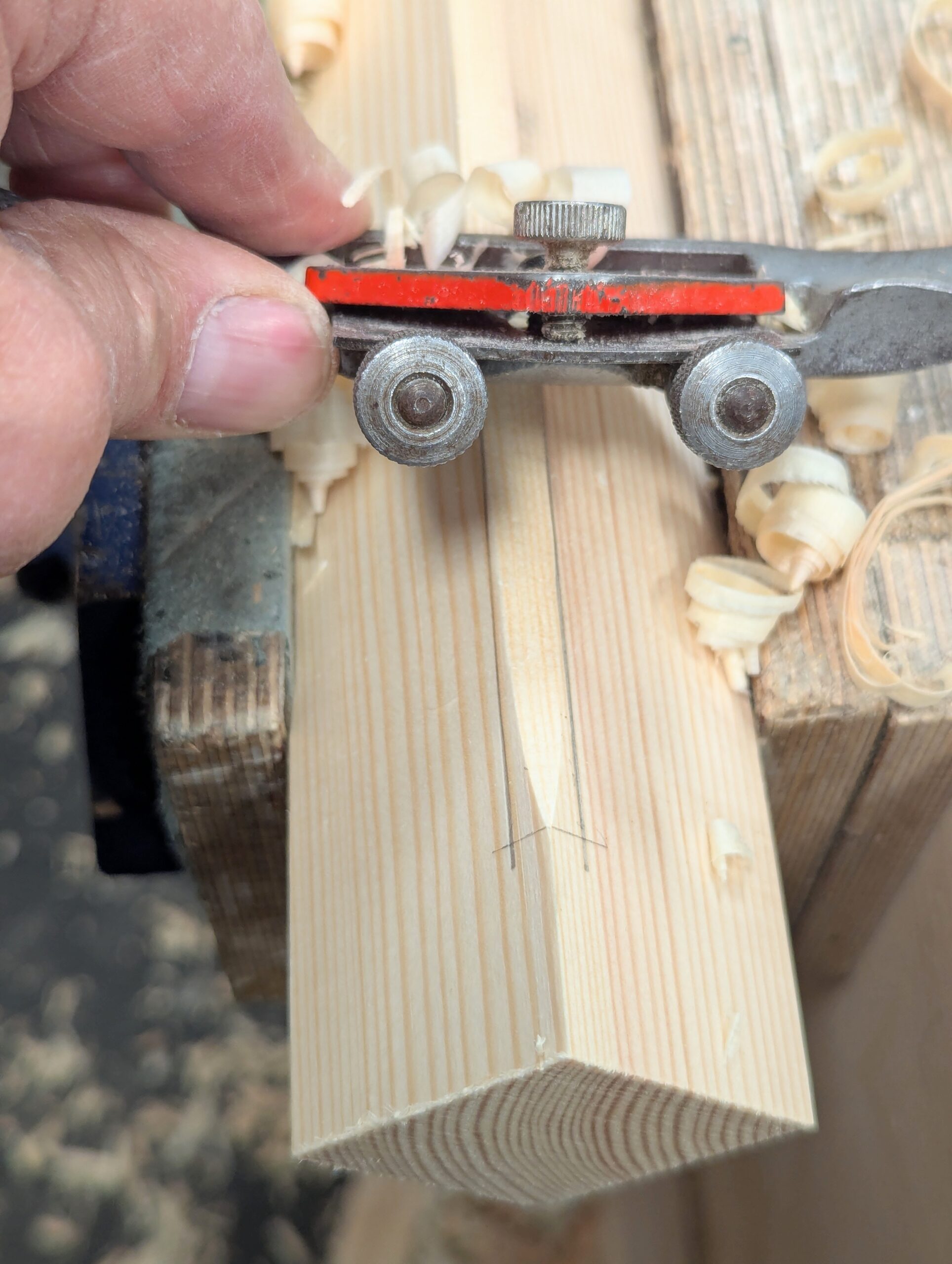
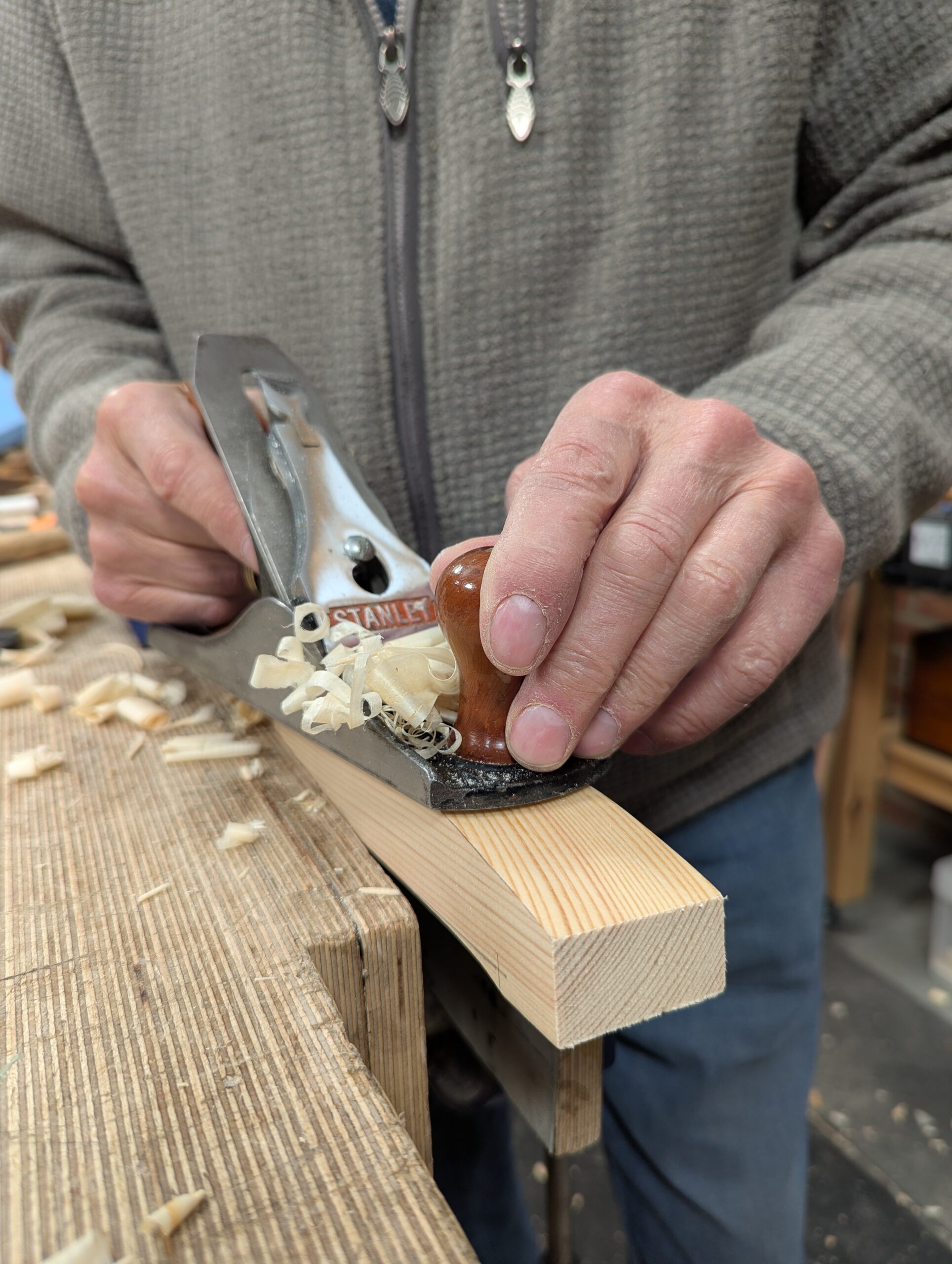
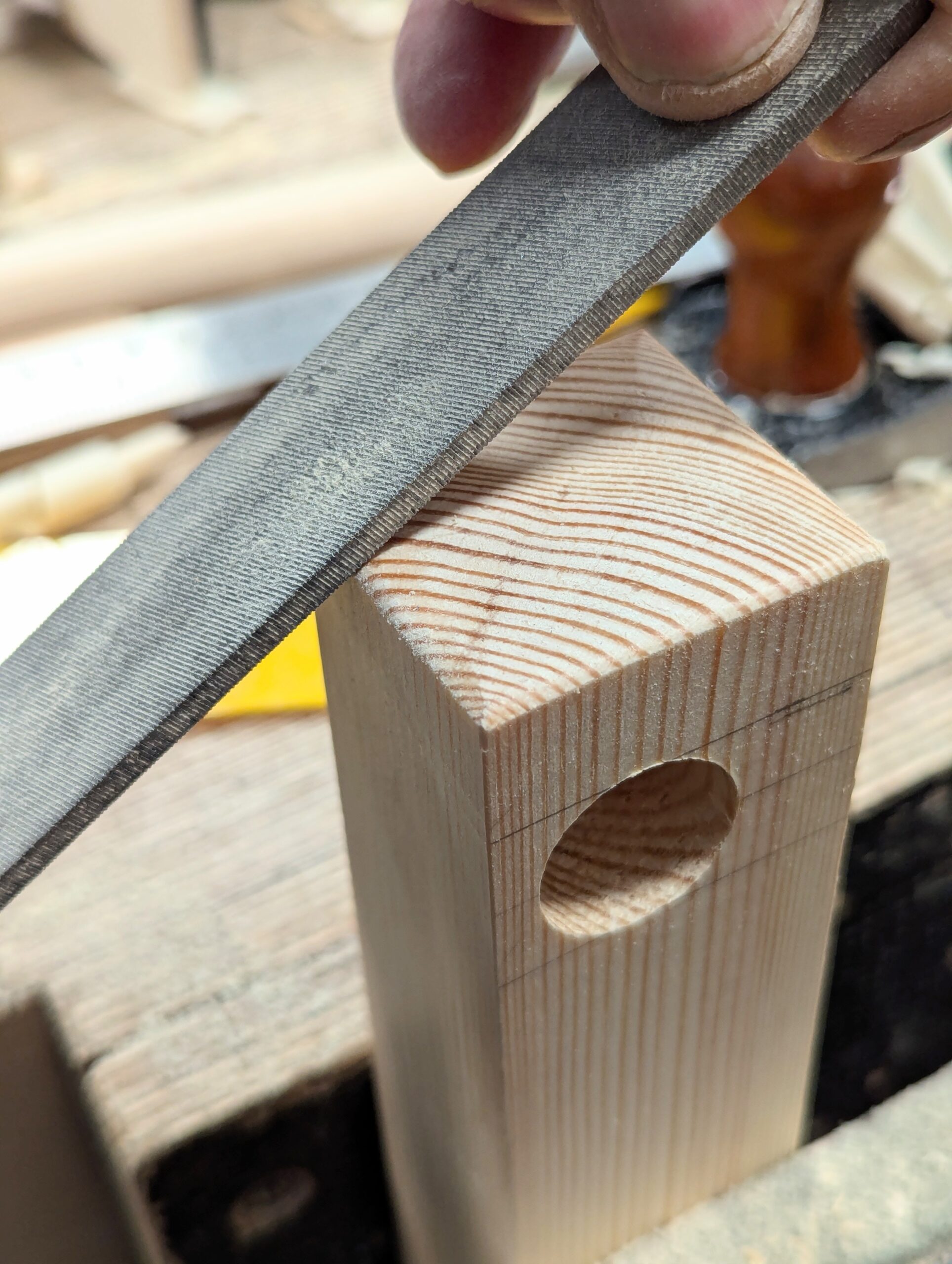
I insert the point of the auger bit into the start hole after first using a twist drill in my drill driver to align a pilot hole to the offcut from my larger guide. This has the angle on it to guide the drill so that later, the auger will follow the initial pilot hole. The predrilling reduces the risk of splitting with the auger bit snail near that vulnerable point, which often happens when boring close to the end of some woods.
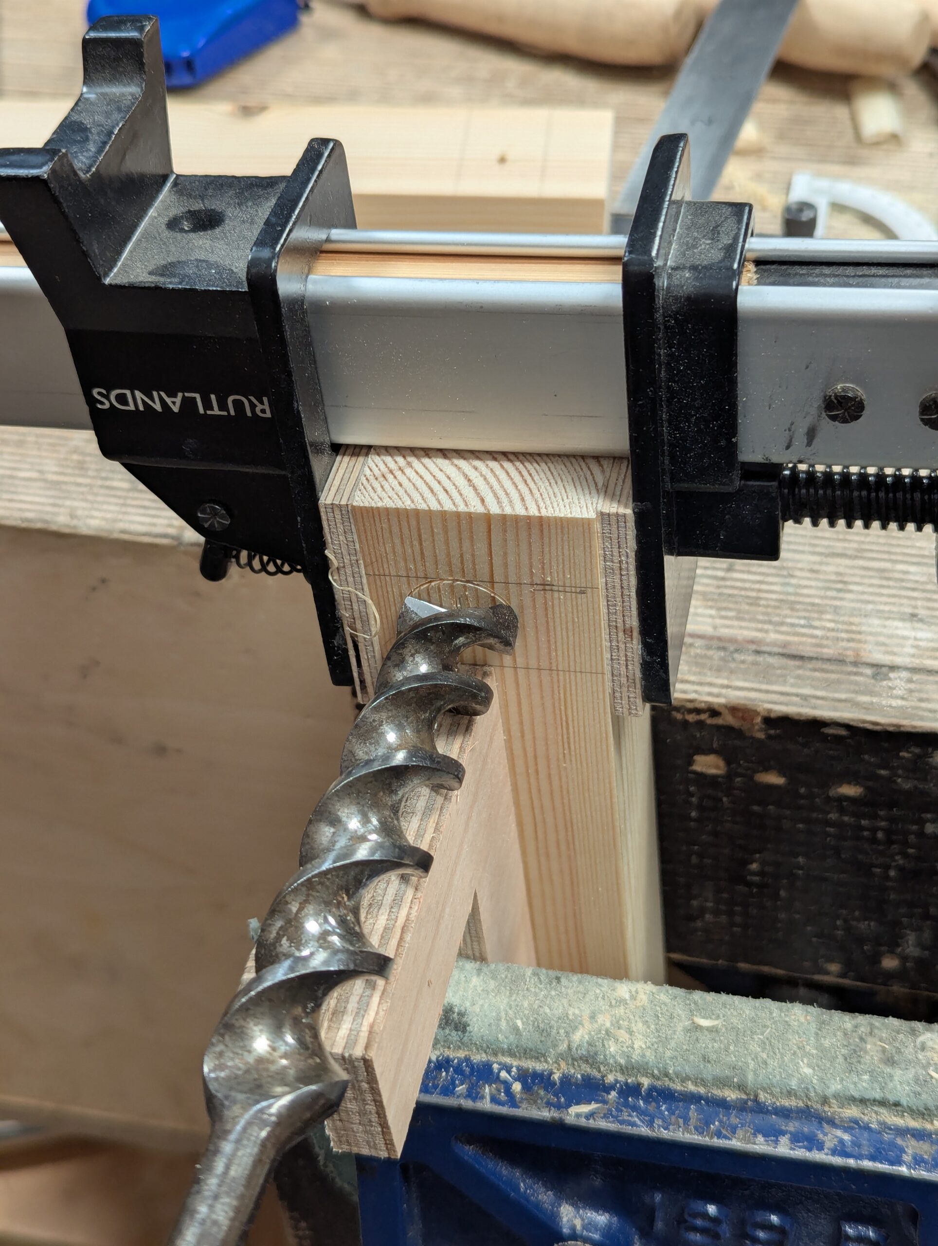
Following this, I align the guide with the rim of the auger bit and start boring. Adding the clamp eliminates any chance of splitting too.
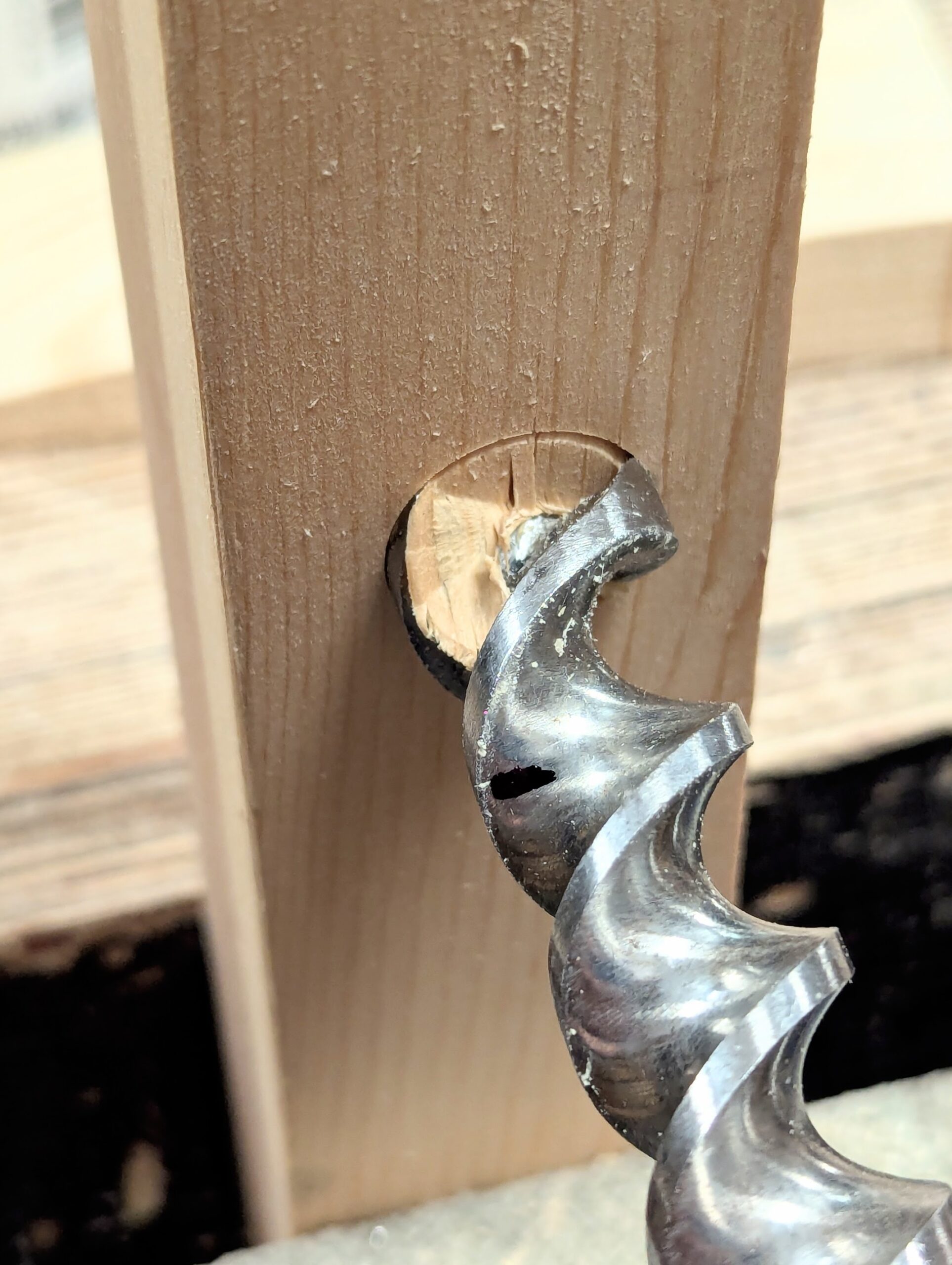
With everything clamped into the vise, I am ready. It's a good idea to use a separate piece of scrap wood to count the revolutions it takes to get to the 3/4" depth. Most people do not know that the pitch of the snail spiral of the auger bits actually controls the level of penetration by each revolution of the brace swing. Mine will likely be different. In my case, with my bit, it took 12 revolutions, so each complete turn of the handle is 1/16". That was very handy, and I was glad to work in imperial increments.
Keeping the bit aligned to the guide makes everything critical to angles as simple as it can possibly be without using a tilt-table drill-press (pillar drill UK). Now I can focus on aligning my bit with the line of the leg in one plane only.
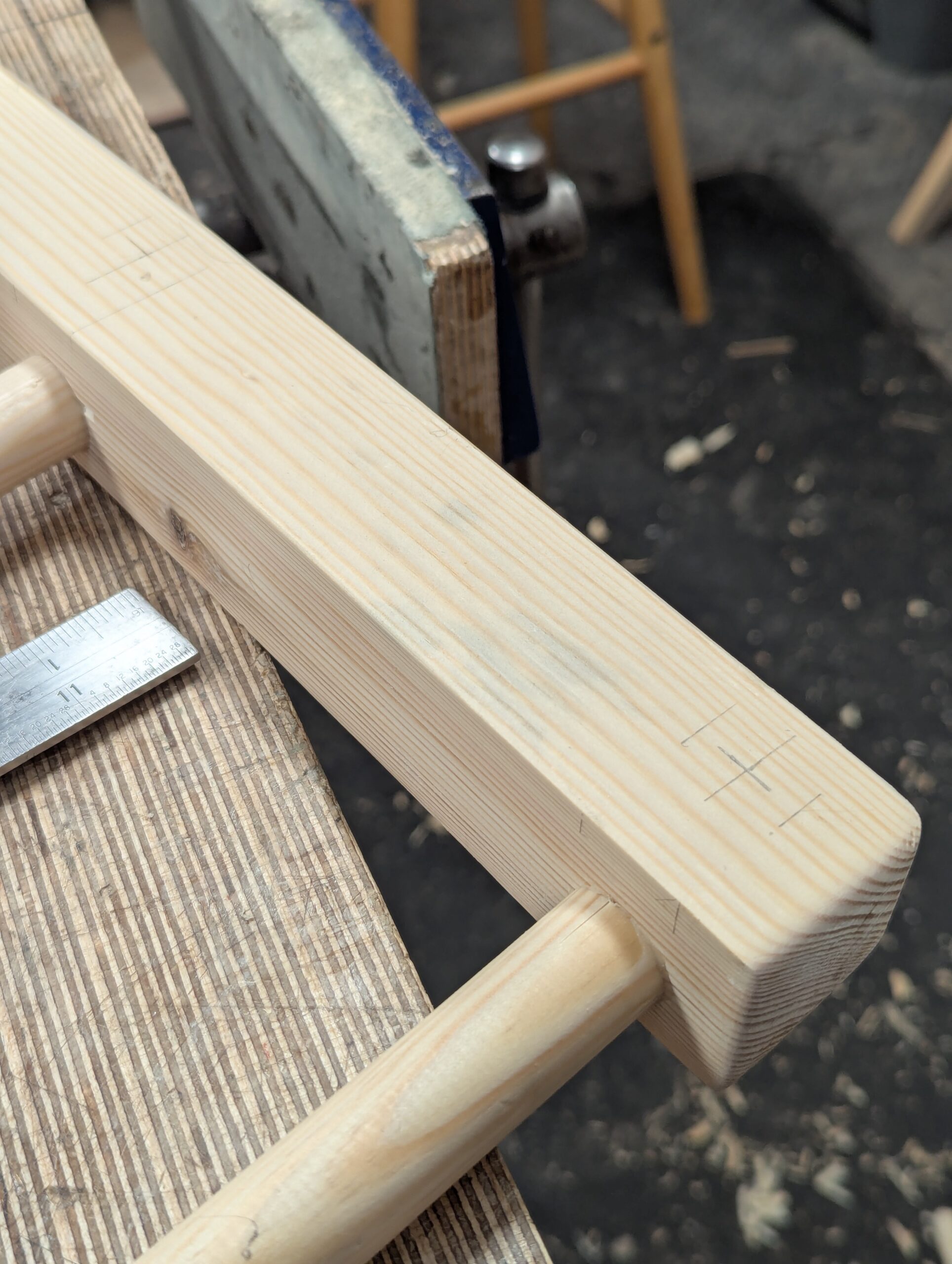
The lower rail will obviously be longer, but the holes are bored the same way.
The lengths for my pieces are, top rails 14 7/8" and lower rails 15 3/4". So four of each length.
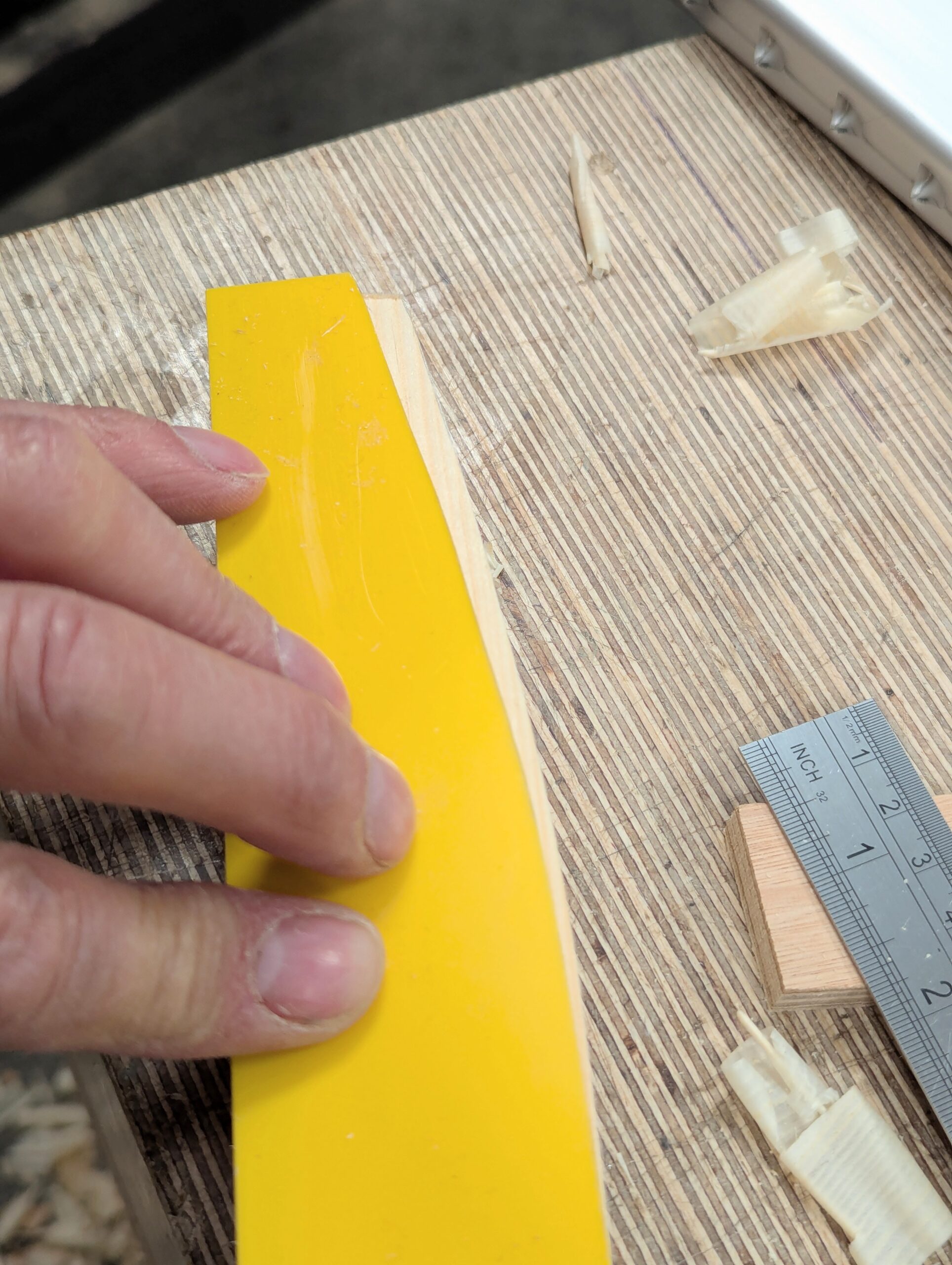
Dry fits become rehearsals and, more importantly, things we learn from. We can tweak and check for twists, see how we can apply pressures to change problem areas, and so on. Clamping reveals the need for tapered pieces to compensate so that the clamps are on parallel surfaces.
Info On the Fox Wedging
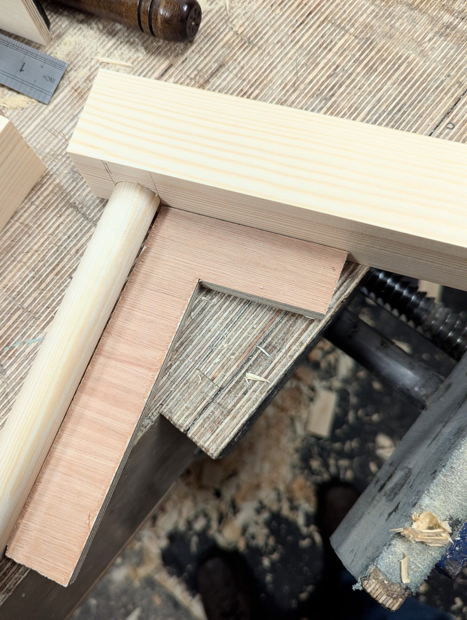
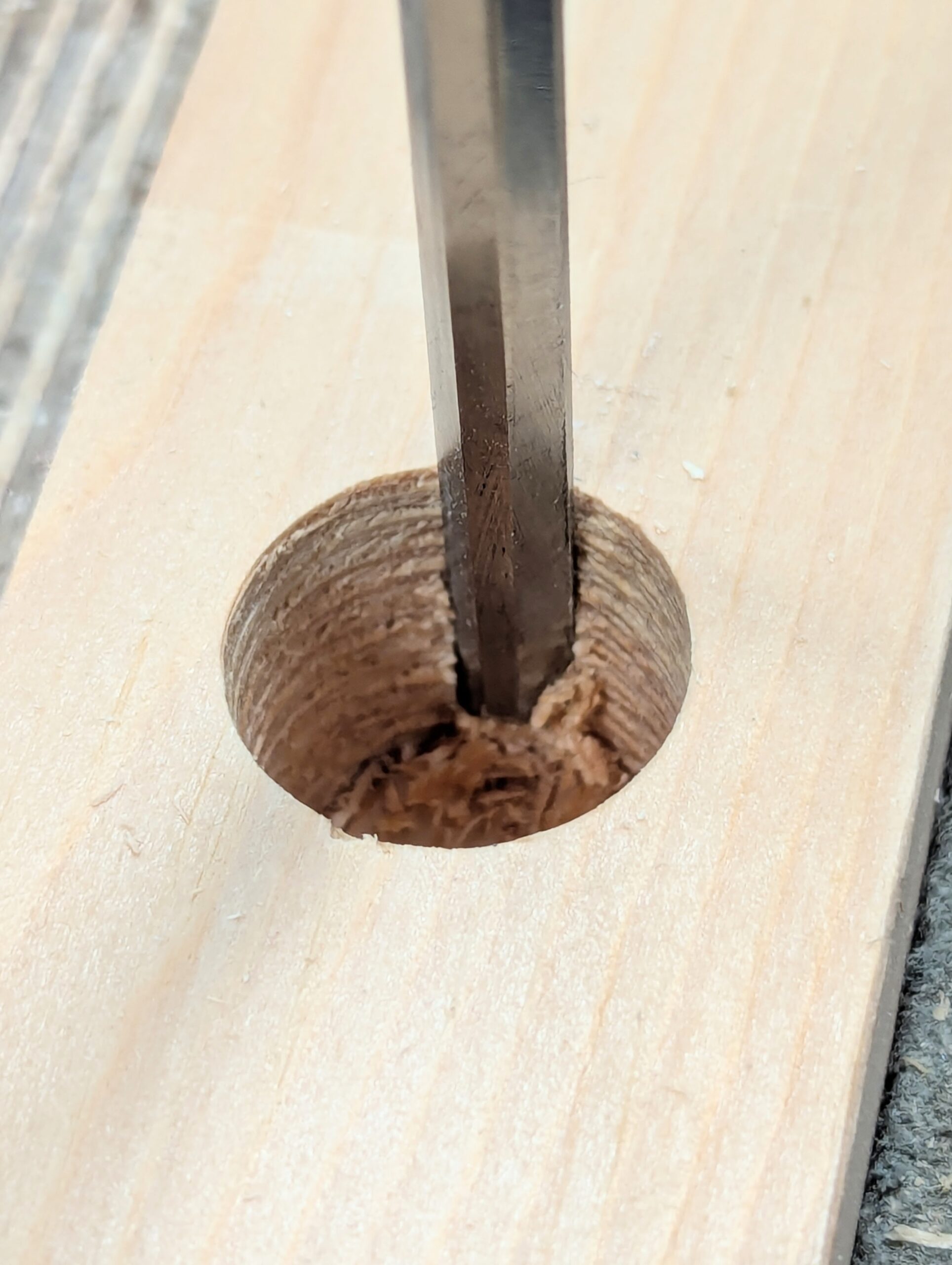
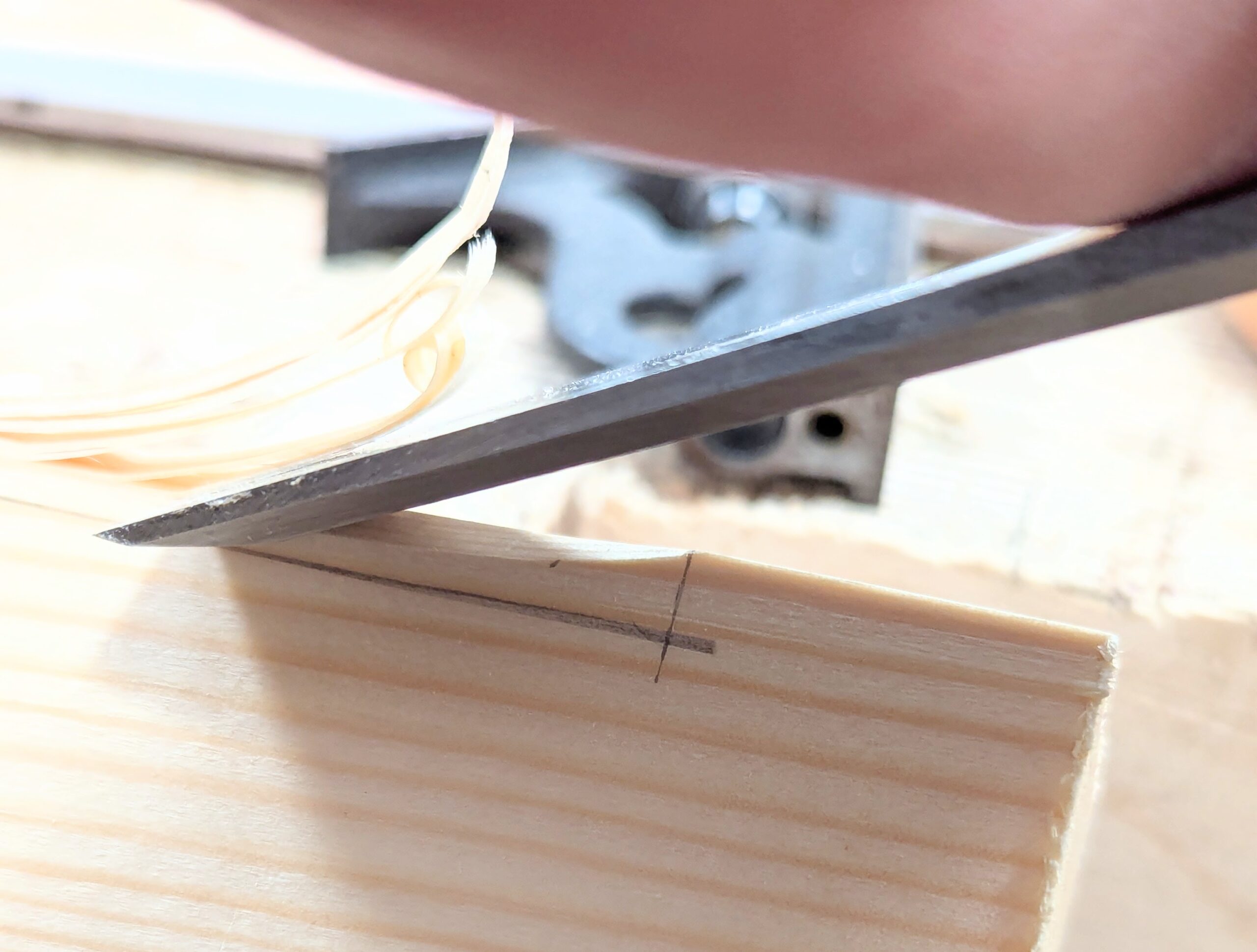
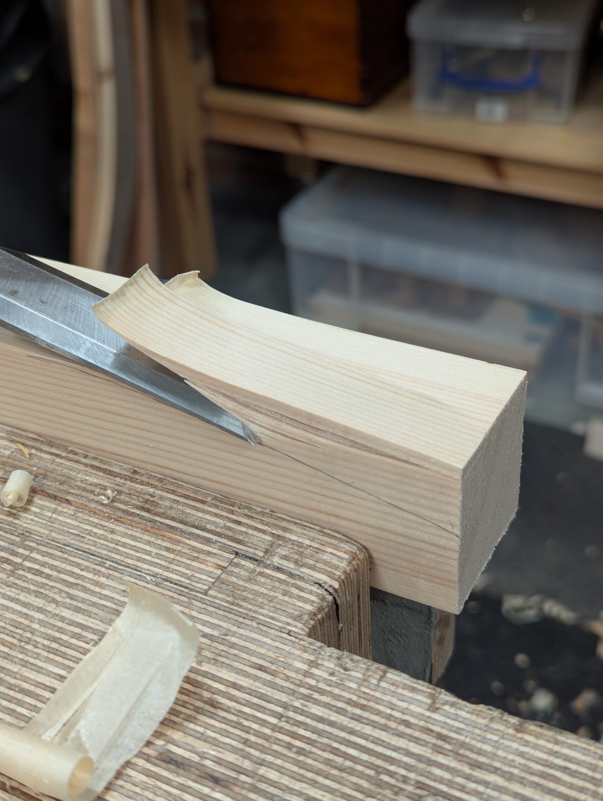
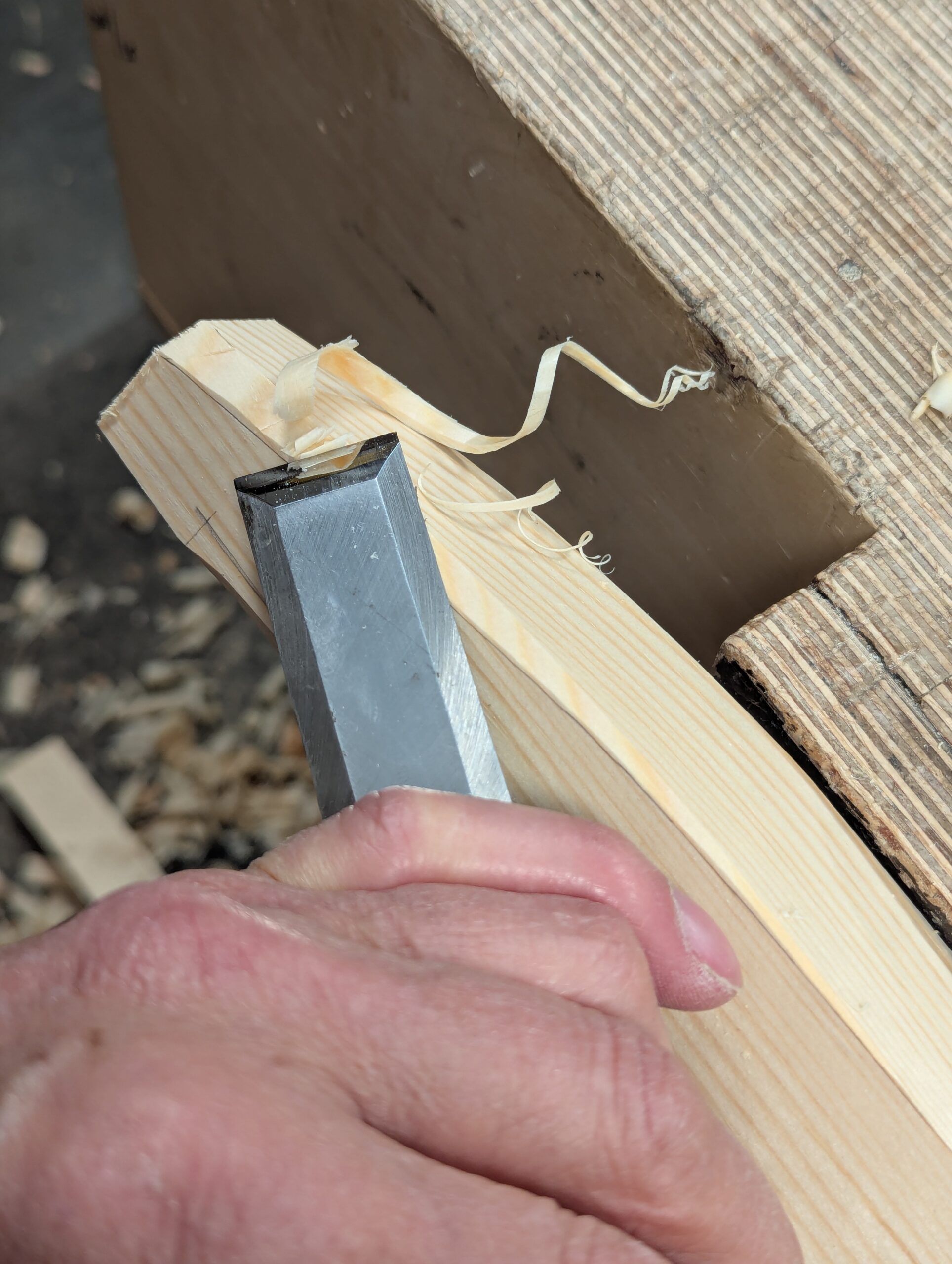
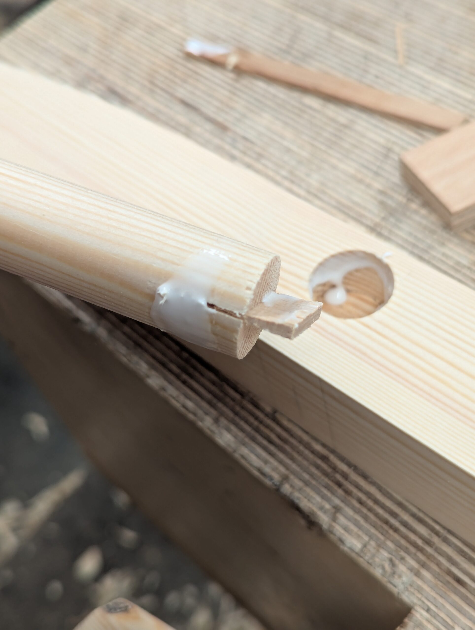
I wanted the wedging to have the pulling power we have in dovetails and then some more. In this case, the circumference is slightly expanded with a narrow chisel undercutting from the rim to the bottom of the hole but not around the whole circumference and only on the bottom of the hole receiving the top rail. When the rail is driven by hammer, the deepening drives the wedge in with each successive blow and the end of the rail expands into more of an oval shape filling the entire recess by both the wedging action and the compression of both the wedge and the rail end. Cutting through this type of joint reveals the effective way it occupies its place with permanence. Once wedged, it will never turn loose.. In this case, we spread the wood into dovetails with wedges. We also cut some
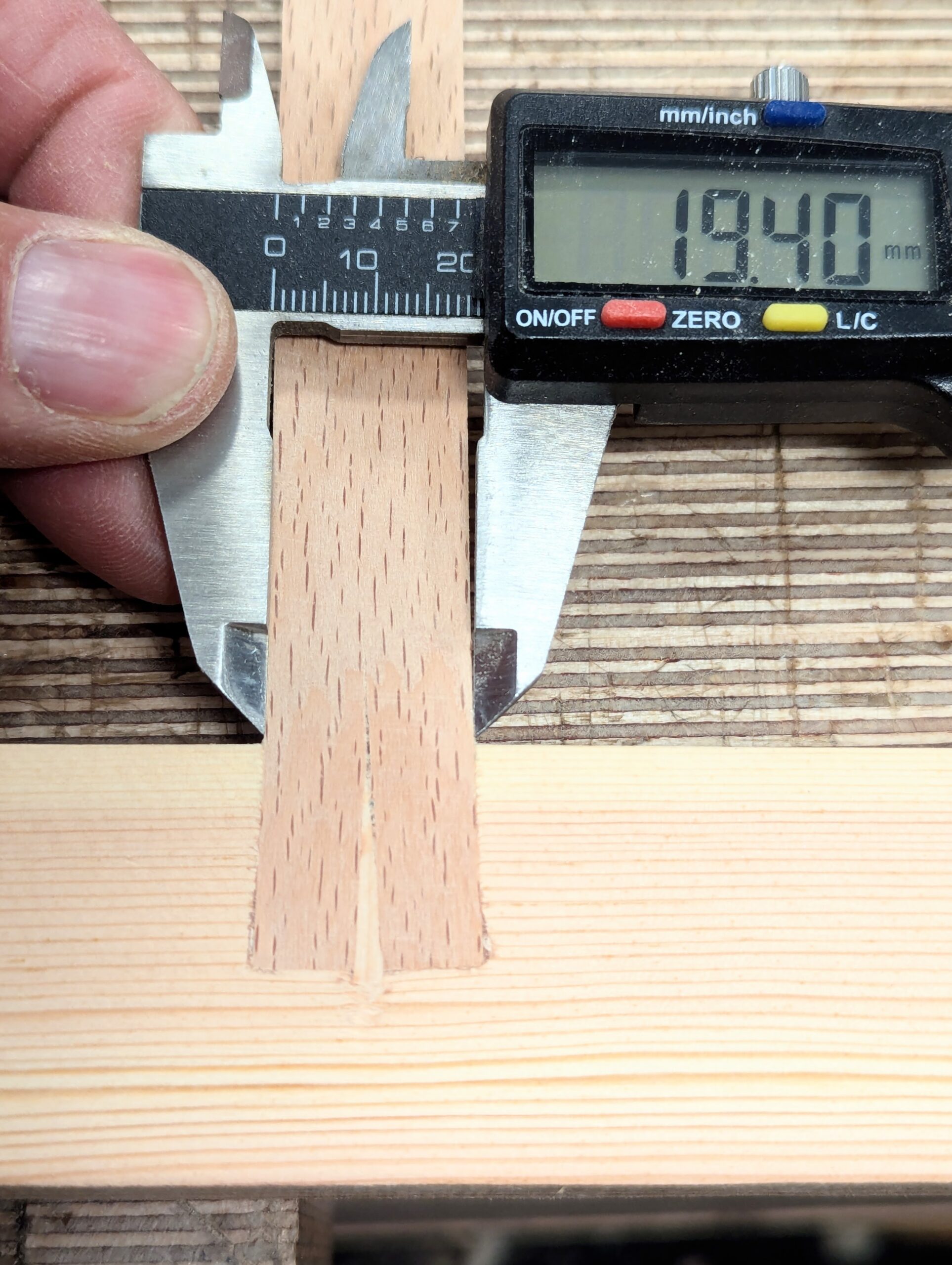
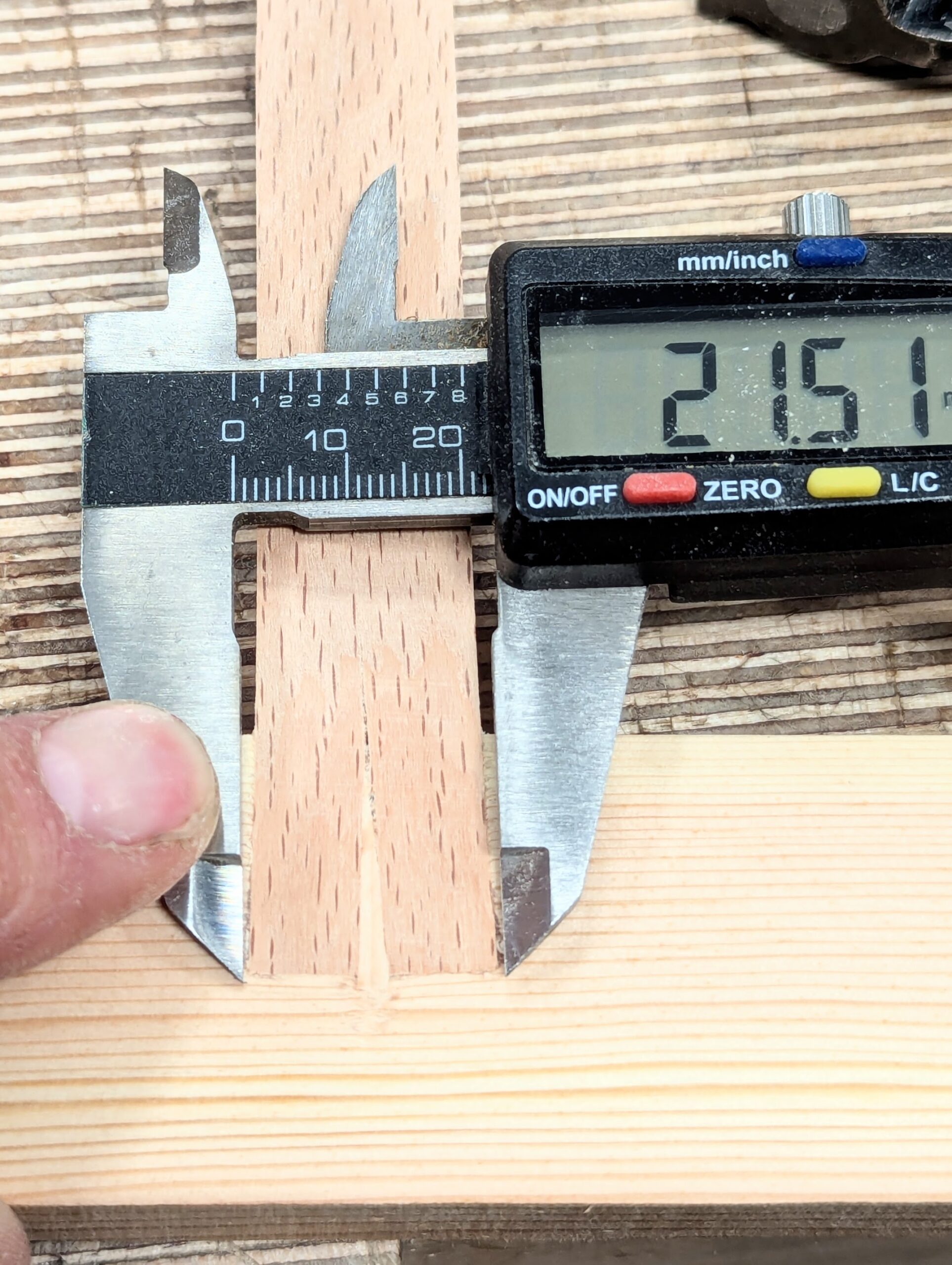
It's a good idea to make a practice piece as shown above. I cut this in two to show how the splay occurs. To allow for the splay, I undercut from the rim of the hole with a 1/4" chisel following the radius of the hole but not all the way around.
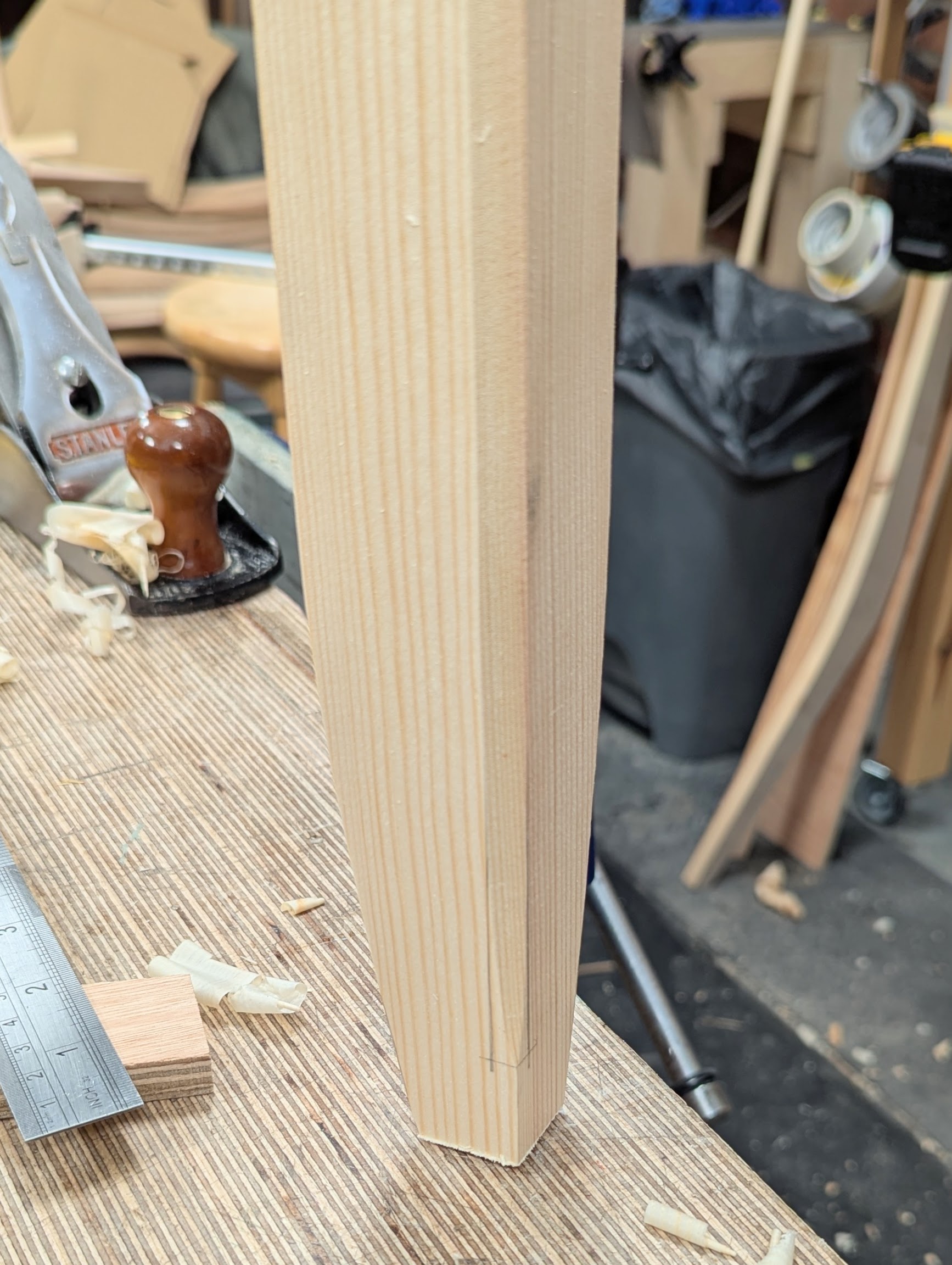
Shaping the Legs
Shaping the legs totally changes the clunkiness of square straights to give a more elegant look. This next part must be done before the rails are wedged in place, if indeed you intend to shape them as I did.
The steps for shaping are as follows:
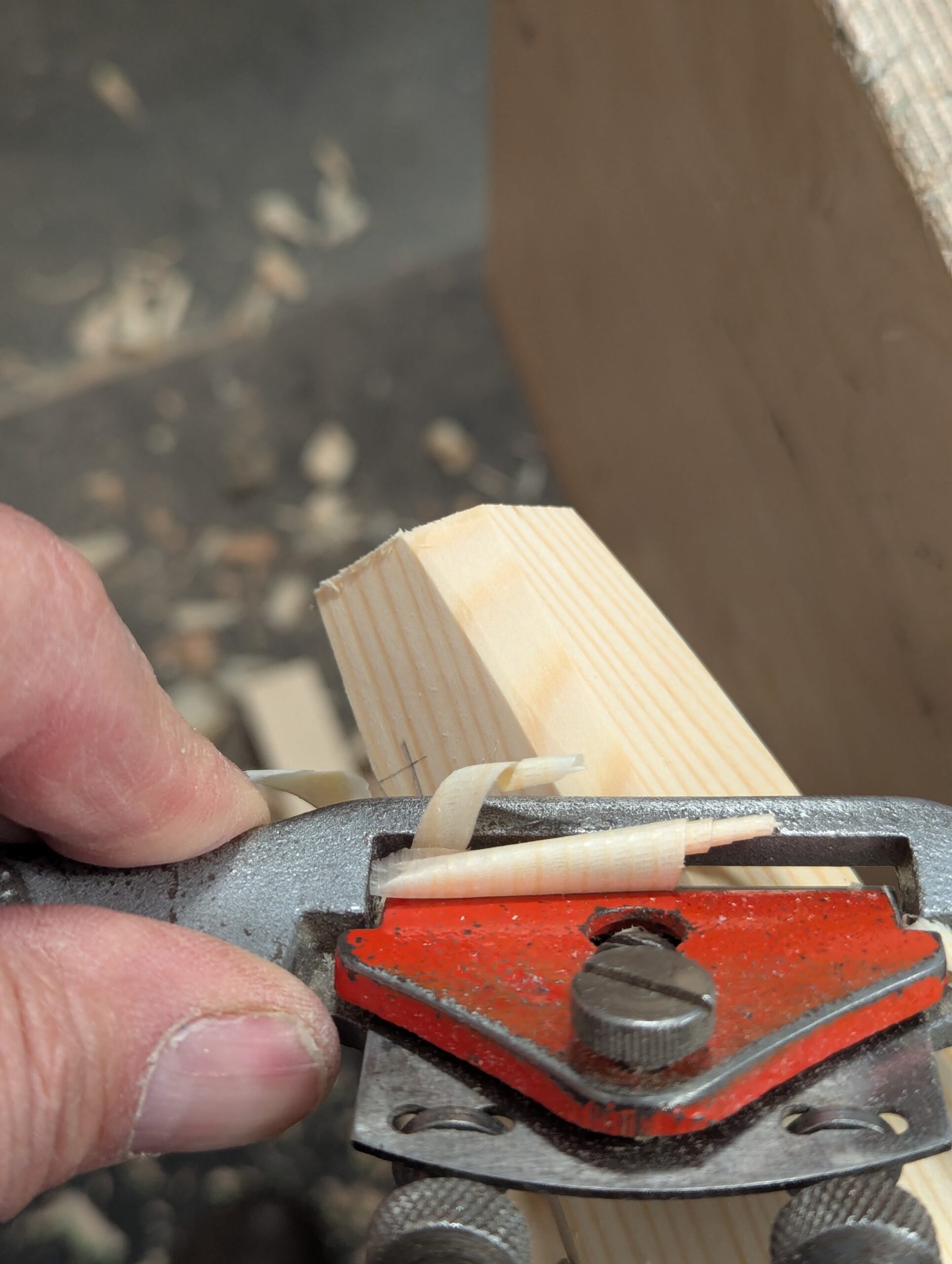

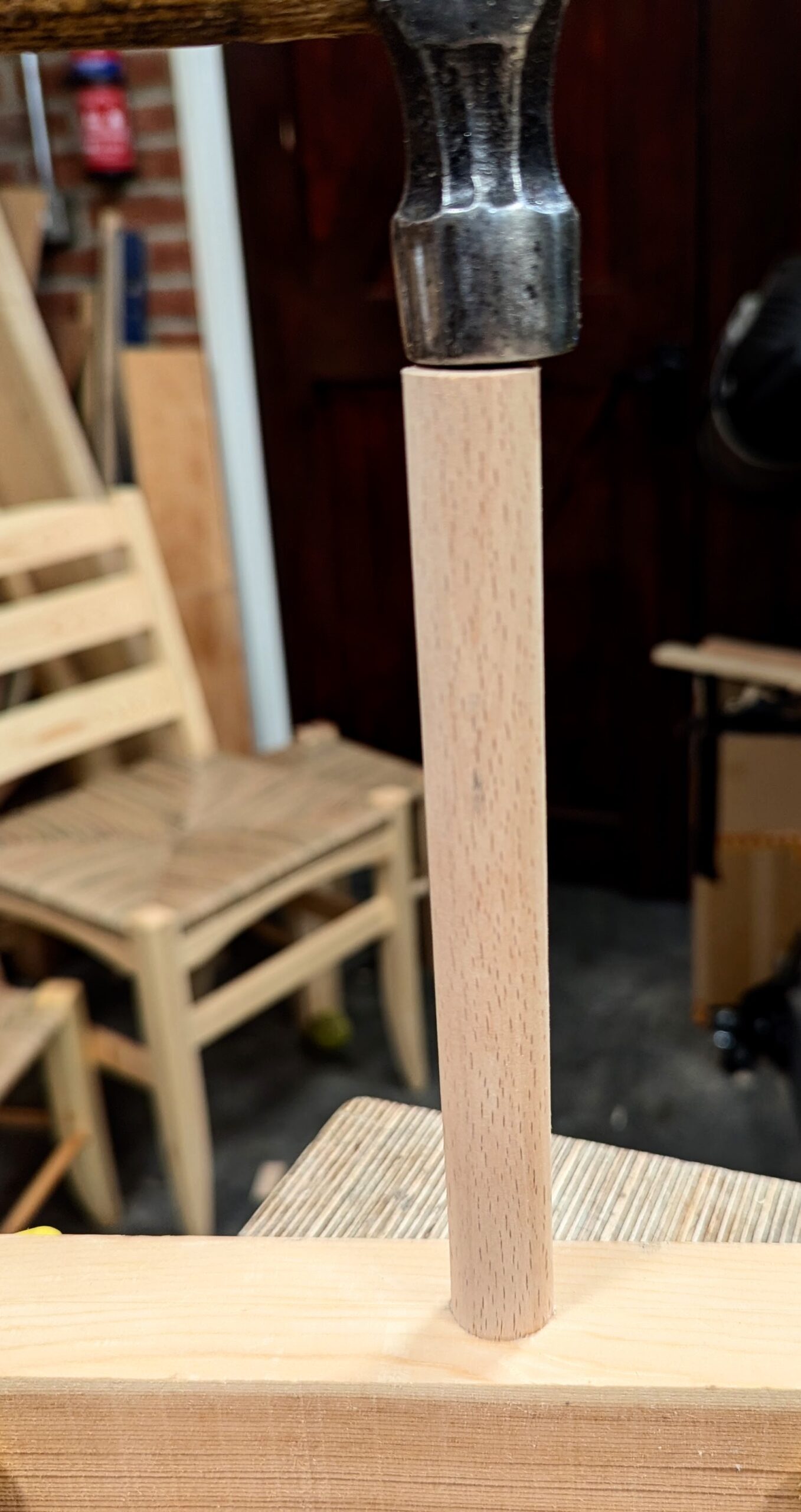
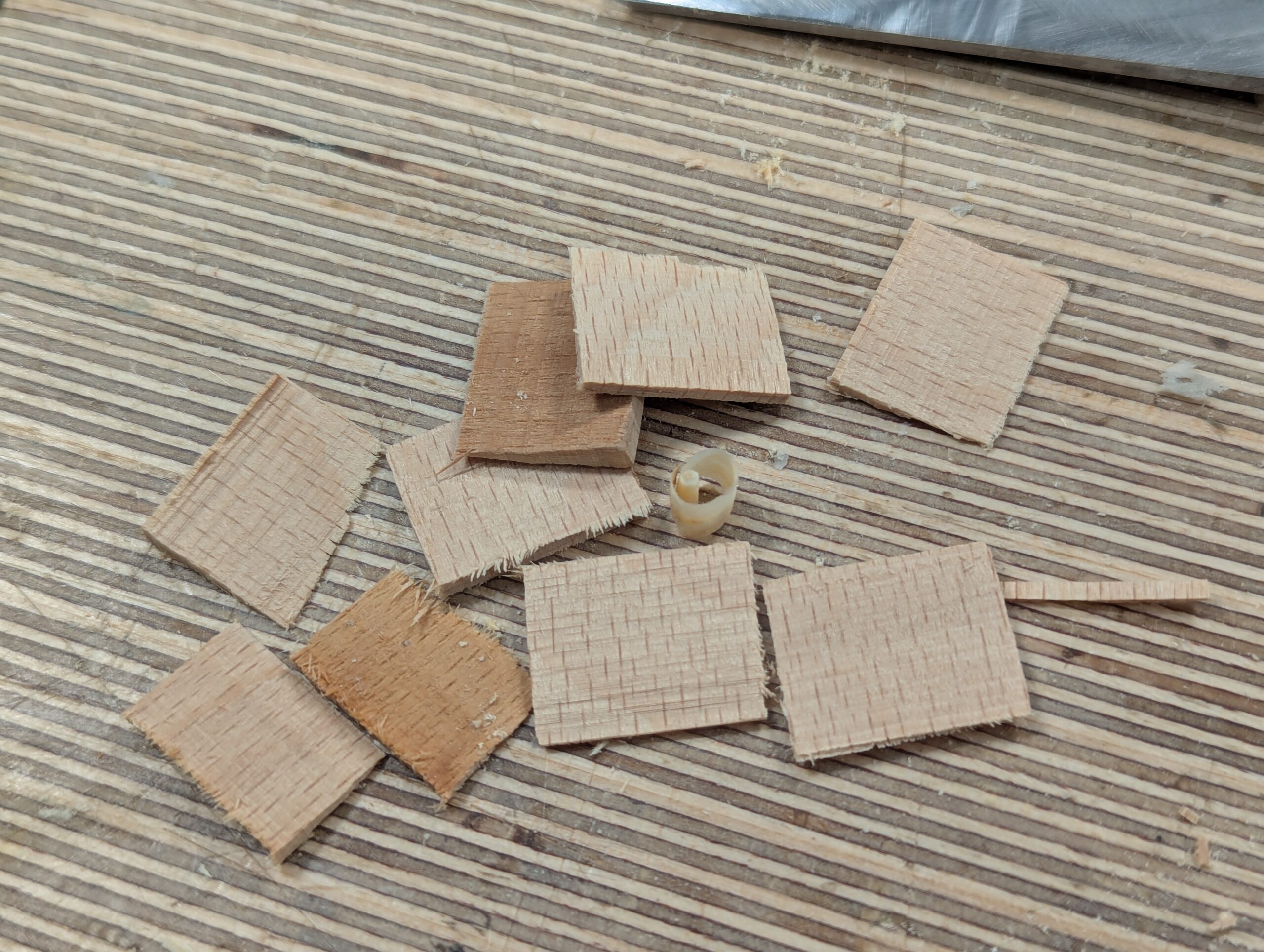
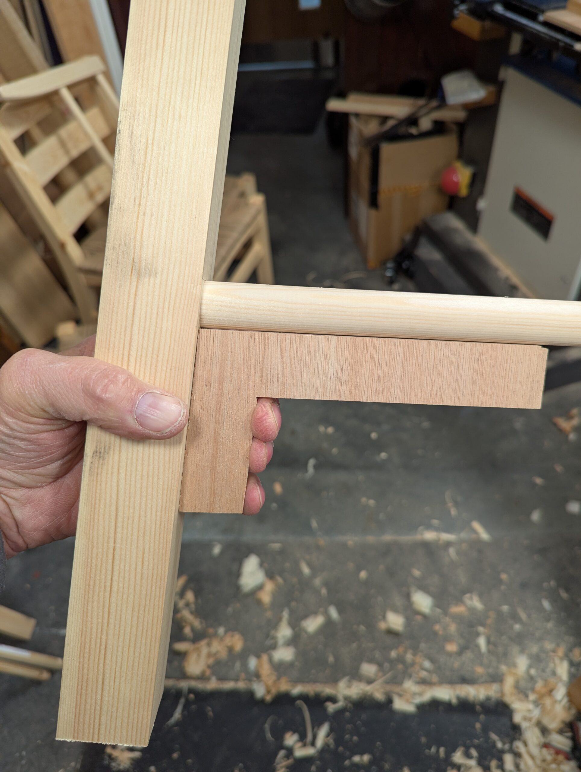
The fox-wedging is permanent and will not allow you to take it apart later once the joint is driven tight, but just after seating the wedge securely, you can still make a minor adjustment to align to the angle guide if you need a small tweak for perfection. I cut the wedges about 1/8" thick at the fat end down to a near feather-edge, about 5/8" to 3/4" but no longer. If too long, they will hold off the end of the rail from seating fully at the bottom of the hole.
Fix the two rails in the one leg first and then add the other leg. I know, it seems obvious, and it can only work one way, but once the wedges are driven, they will not let go.
Remember, it's worth mentioning again, aligning the saw kerf directly across the grain of the leg is also a critical point too. Placing it the other way will most likely split the leg when you drive it home; especially at the top of the leg, where the grain is shorter.
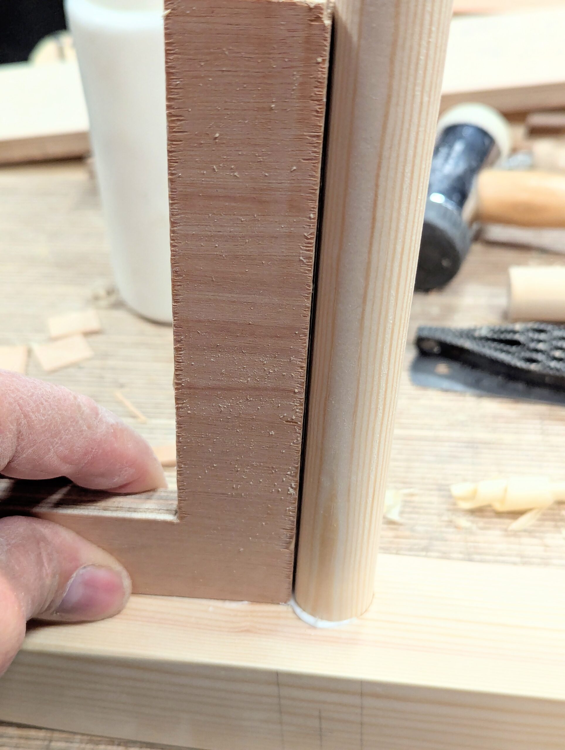
After glue up, immediately sight one leg to the other or one rail to the other, as the frame can be twisted and can still be corrected at this point if needed. Once the glue is dried, it cannot be corrected, so check straight away and don't delay.
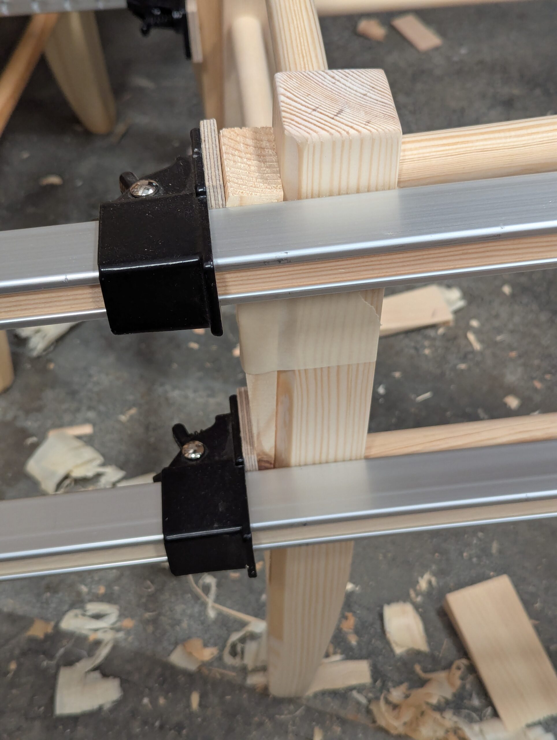
I suggest you set the frames aside for the glue to dry. Four hours ensures a thorough bond––overnight is even better. This time allows all the grain fibres to expand and permanently interlock for integration. When you begin to bore the next holes adjacent to the originals, the added resilience maximises resistance against the rigours of driving all four rails into the sockets at the same time and then too possible clamping as well.
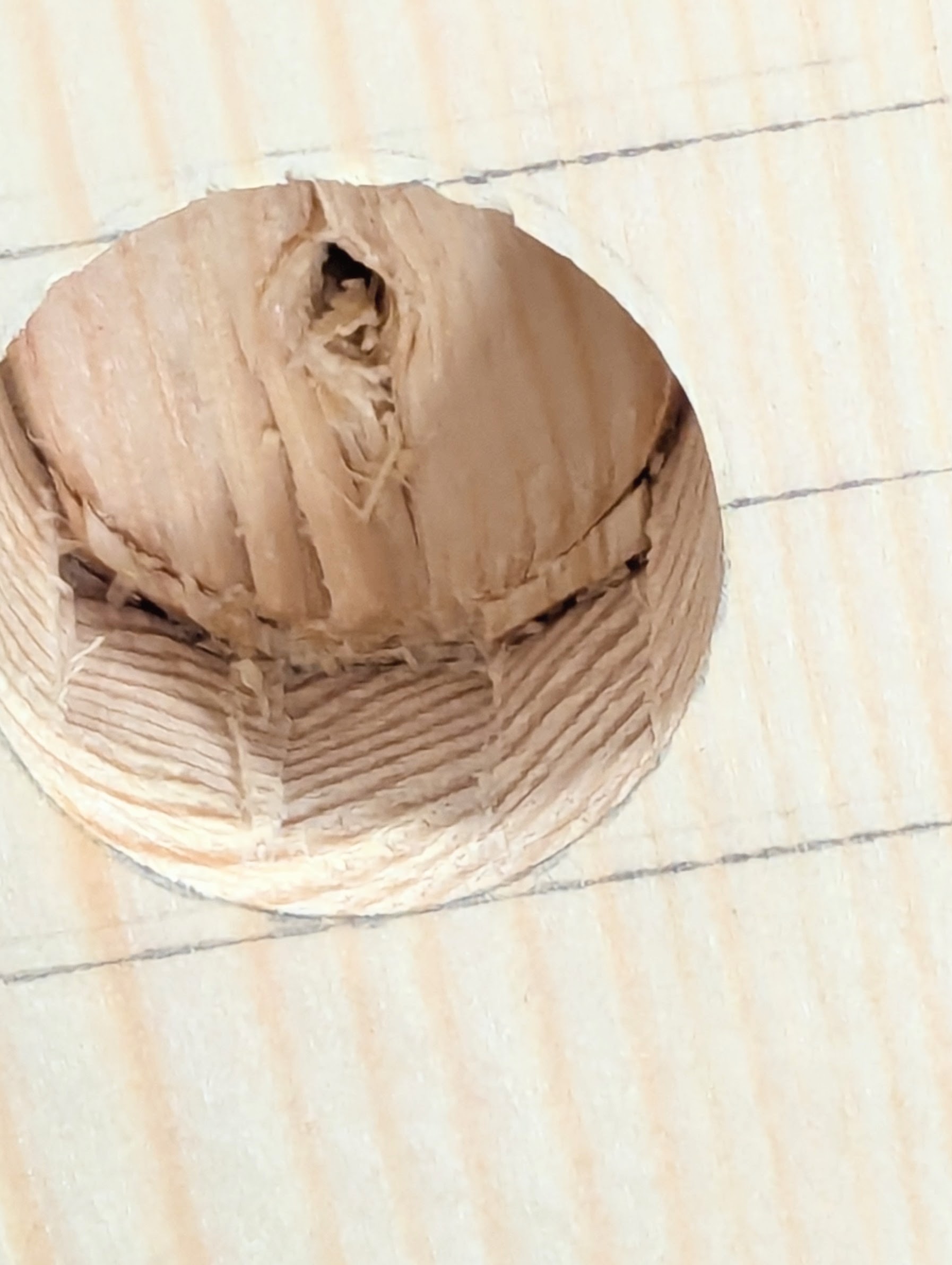
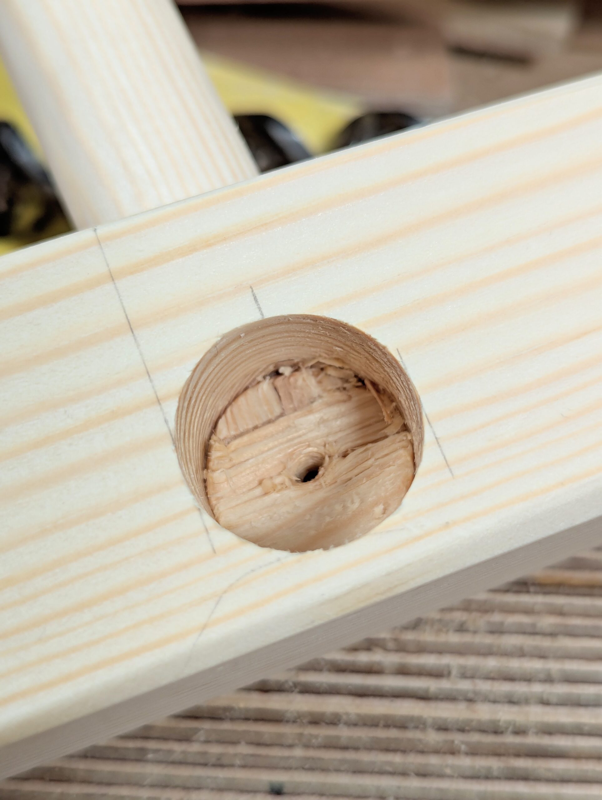
Below, looking to the bottom of the hole, you will better understand why we did not bore these holes at the same time as the earlier ones. Without the rail secured in place, the bottom of the hole would have bust out of the unsupported fibres. There is a 1/8" at the end of the rails that we bore into because of the 7/8" diameter dowel size. In other words, we clip the end when we bore with the brace and bit. The fully seated and glued rail, fully wedged, ensures a solid seat area to the rail when we drive the wedges into the rail ends.
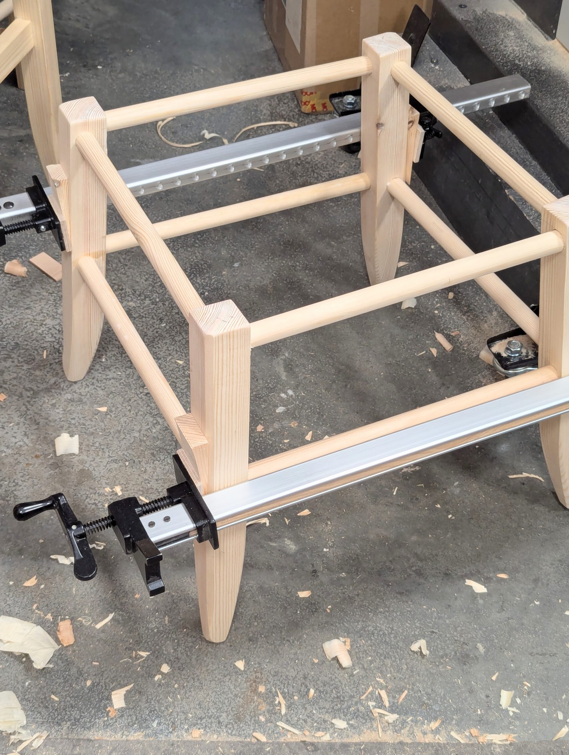
A dry assembly with clamps followed by measuring to check distances and everything seats well is the best plan before gluing the four rails. You are now ready to glue the four rails into one of the frames. Make sure you get the right rails into the right holes and that the kerf is aligned across the long grain or axis of the legs. I prefer to add clamps with long tapered pieces counterpoised to the splay of the legs after driving the rails home in all of the eight holes. You can pinch the smallest fractions of an inch this way.
After gluing, check again for twist by sighting one rail across to another.
When the frame is completed and the glue dried, it's a good time to apply a protective finish. I used two coats of hard wax finish.
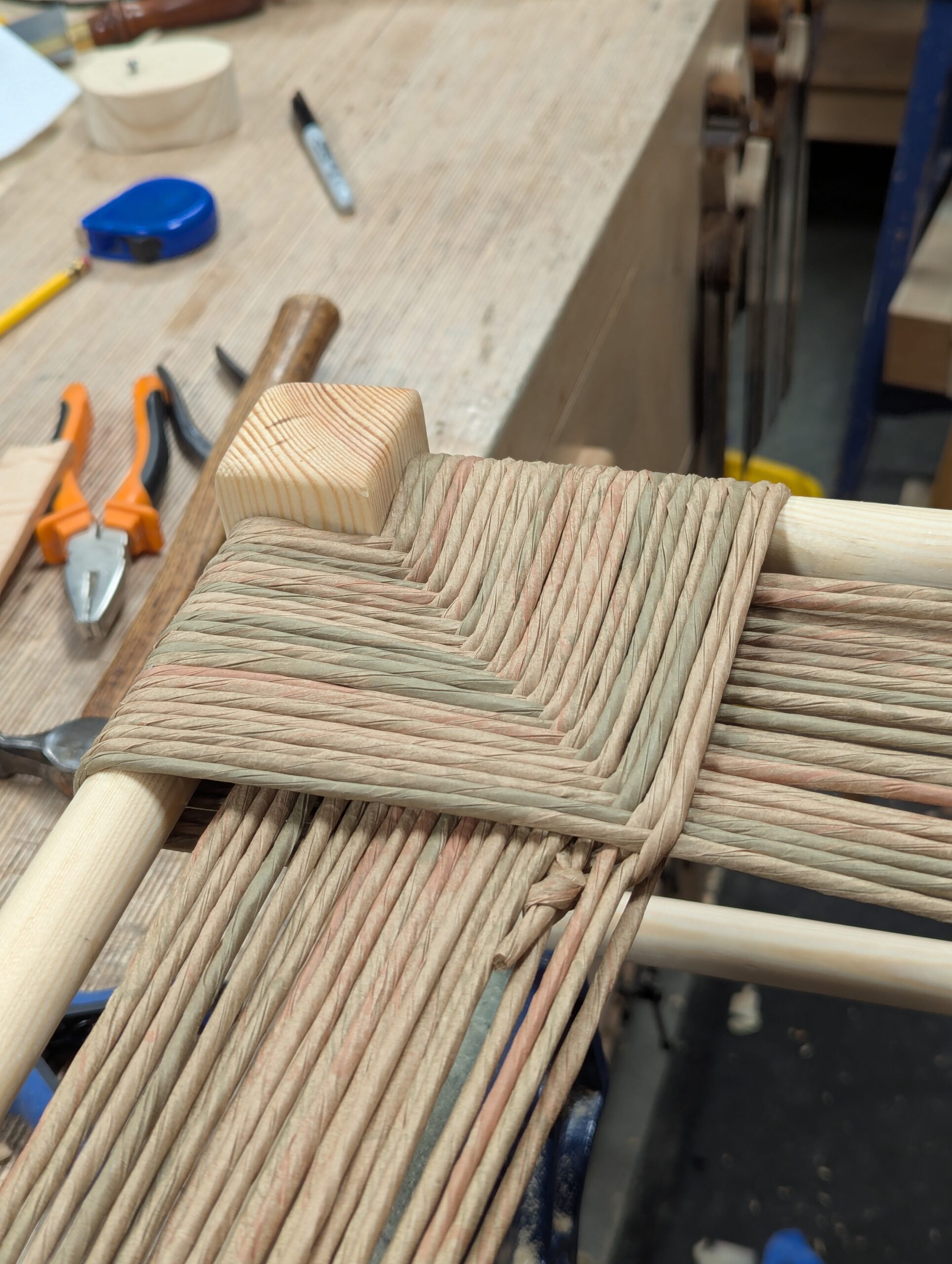
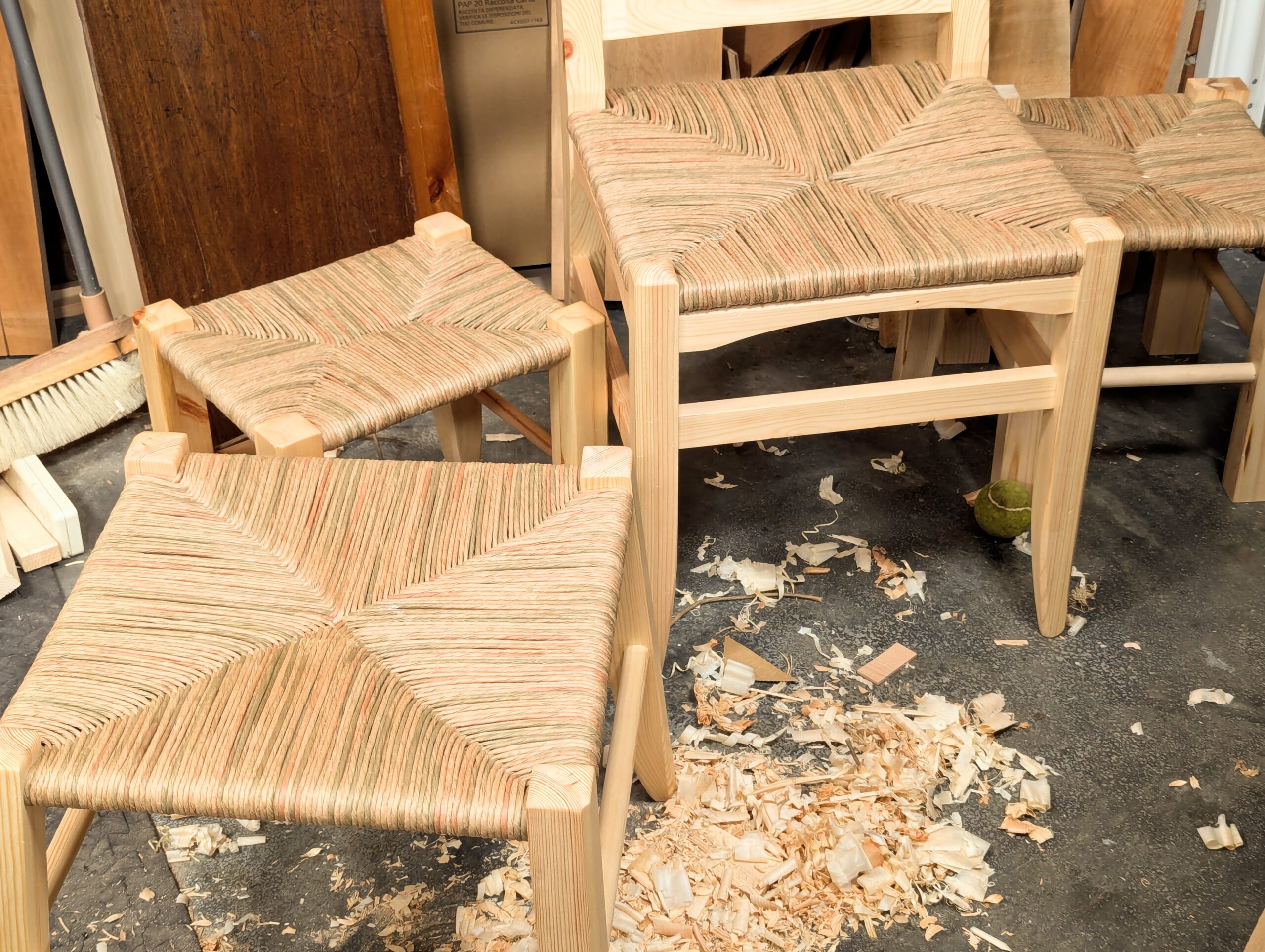
The next blog post will be about the weaving of the seat. It's a simple pattern that well suits this type of stool and a whole range of others too. I used it on my office chair for the last Sellers' Home project. Episodes 1-4 are out now. Here's the link to the current and upcoming episodes.
Comments ()