Your Tenon Tightening Technologies
Tenons can simply be glued. We do it all the time and gluing them lasts just fine. Mostly we rely on clamps to seat shoulder lines and and keep the two parts married until the glue dries. When this has taken place it is unlikely you will ever be able to part the union without damaging one or the other or indeed both. It was and still is for some a marriage made in heaven!
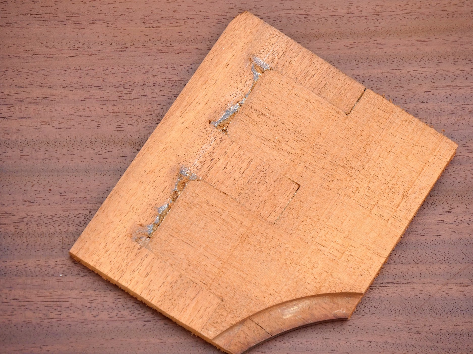
Before the advent of the screw thread and the now ubiquitous clamp that we derive our effortless clamping power from, craftsmen relied on the draw-bore method for seating joint lines and drawing up the tenons. On long rails that defy clamping we still use the draw-bore method for drawing up the tenon into the final union and indeed this method, as long as the shoulders were dead square, guaranteed that the outcome of frame making like sash windows, doors and window frames were indeed square. All too often we fail to realise that clamps misaligned to the long axis of the rails will clamp frames out of square because they will compress the stile fibres into a crushing submission. A well placed draw-bore hole and pin does not do this. Draw-boring mortise and tenon joints relies on two offset holes being bored separately in both the stile and the rail. The hole in the stile or leg, through the mortise hole and near to where the tenon shoulder meets the stile or mortise hole, is first bored all the way through or at least part way into the second half if not bored all the way through. Then the tenon is pushed into the hole so that the tenon shoulder fully seats. To seat the joint full we use tapered metal pins called draw-bore pins. Driving or manipulating these into the hole when the joint is together pulls the two parts tightly together. Placing the point of the auger bit back into the hole so that the snail point of the bit touches the tenon inside gives the exact centre of the position of the hole through the mortise. With the tenon withdrawn, we now bore a slightly offset hole nearer to the shoulder of the tenon but aligned centrally to the original hole. This distance will vary depending on the size of the stock. Timber frames for timber framed structures such as buildings may be offset 6mm and more whereas small wooden frames say for chair legs and rails need only be offset 1 or 2mm. The round peg, when driven, compresses at the intersection of the two holes, where they crossover, and the peg remains distortedly less in diameter on the exit side of the hole. Hence there is usually a gap on the exit hole side around the peg. This cutaway shows how the peg bends to conform to the offset and remains this shape for the lifetime of the joint. A sort of internal spring if you will.
Wedging
Wedging generally relied on clamping for seating the shoulders. Why use wedges? In the early days of screw threads and iron clamps the clamps were expensive and few and far between. Not like today when most woodworkers own a dozen or so. Clamping followed by wedging meant the clamps could be used immediately on the next frames so as soon as the wedges were driven the clamps were removed to be used elsewhere.
The simplest of wedging was drive the wedges alongside the tenons. This was quick and effective but lazy. Here, the tenon is not cut to receive the wedges either side but the fibres of the tenon are compressed.
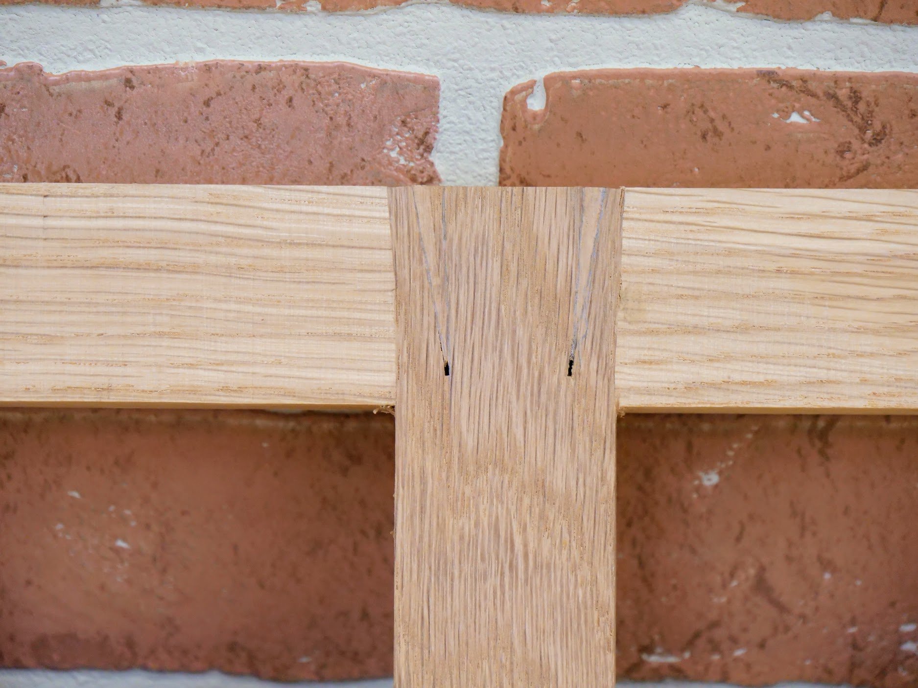
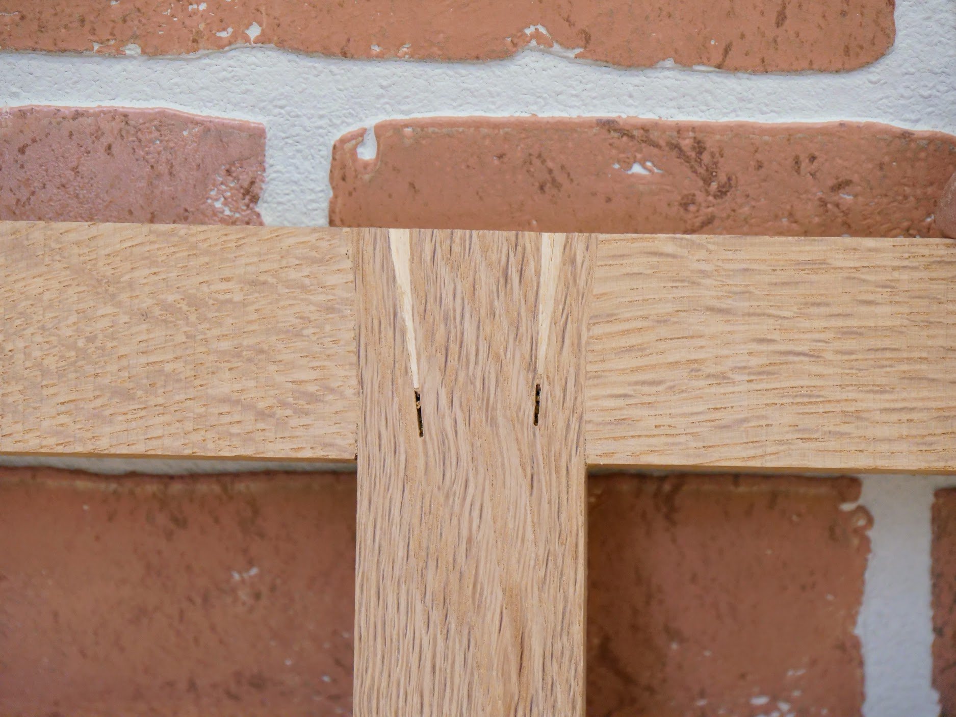
The next type of wedging was to simply drive wedges into saw kerfs cut into the tenon parallel to the long axis and allow the wedges to create pressure in the width of the joint, compressing the tenon width between the extremes of the mortise.
Another type is to slope the saw kerfs as cuts which send the tips of the wedges toward the inner reaches of the tenon. Opening up the outer aspect if the mortise creates a dovetailing effect. This is very strong and resists breaking off the outer aspect of the tenon which sometimes happens with the former method above.
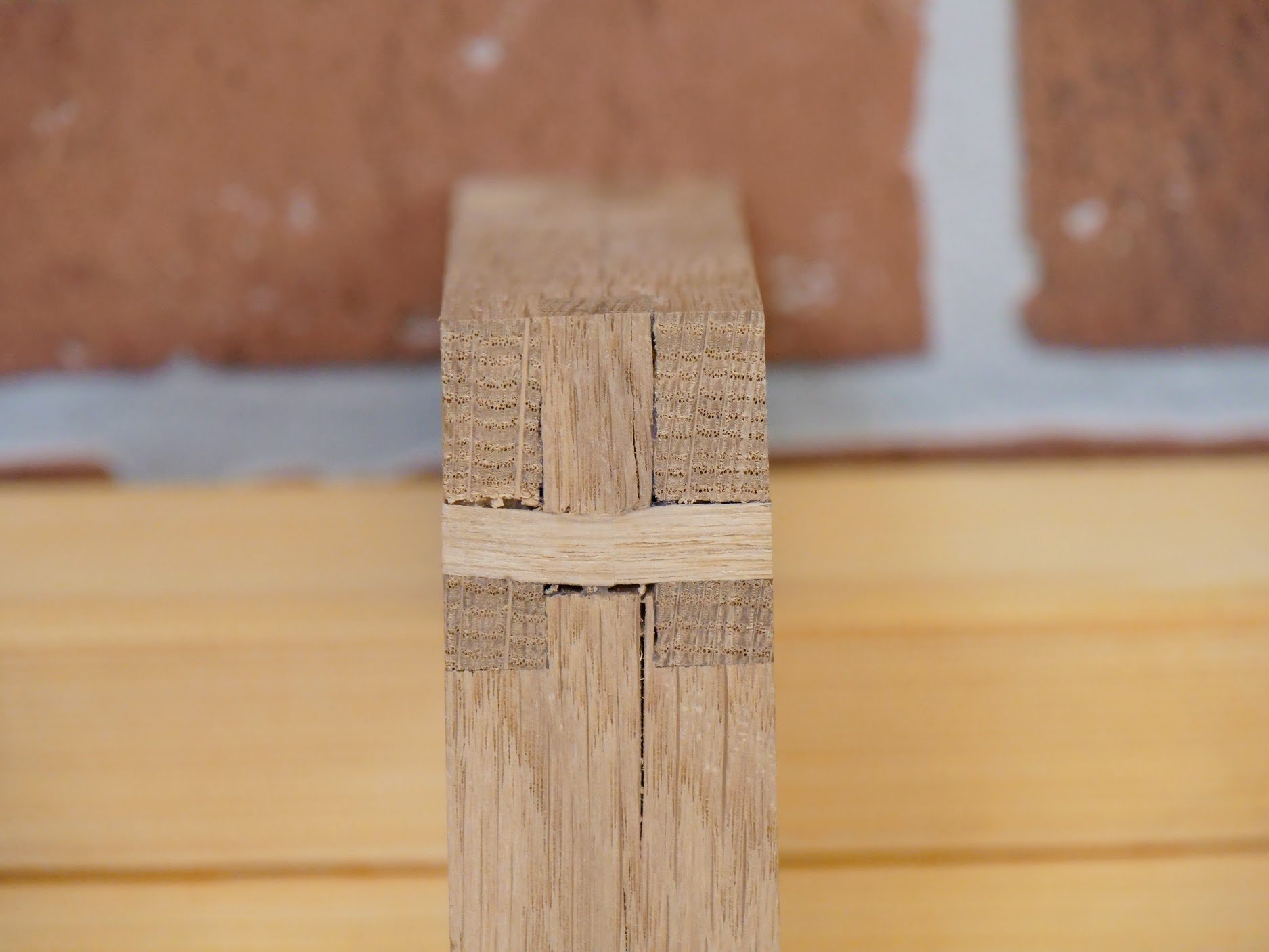
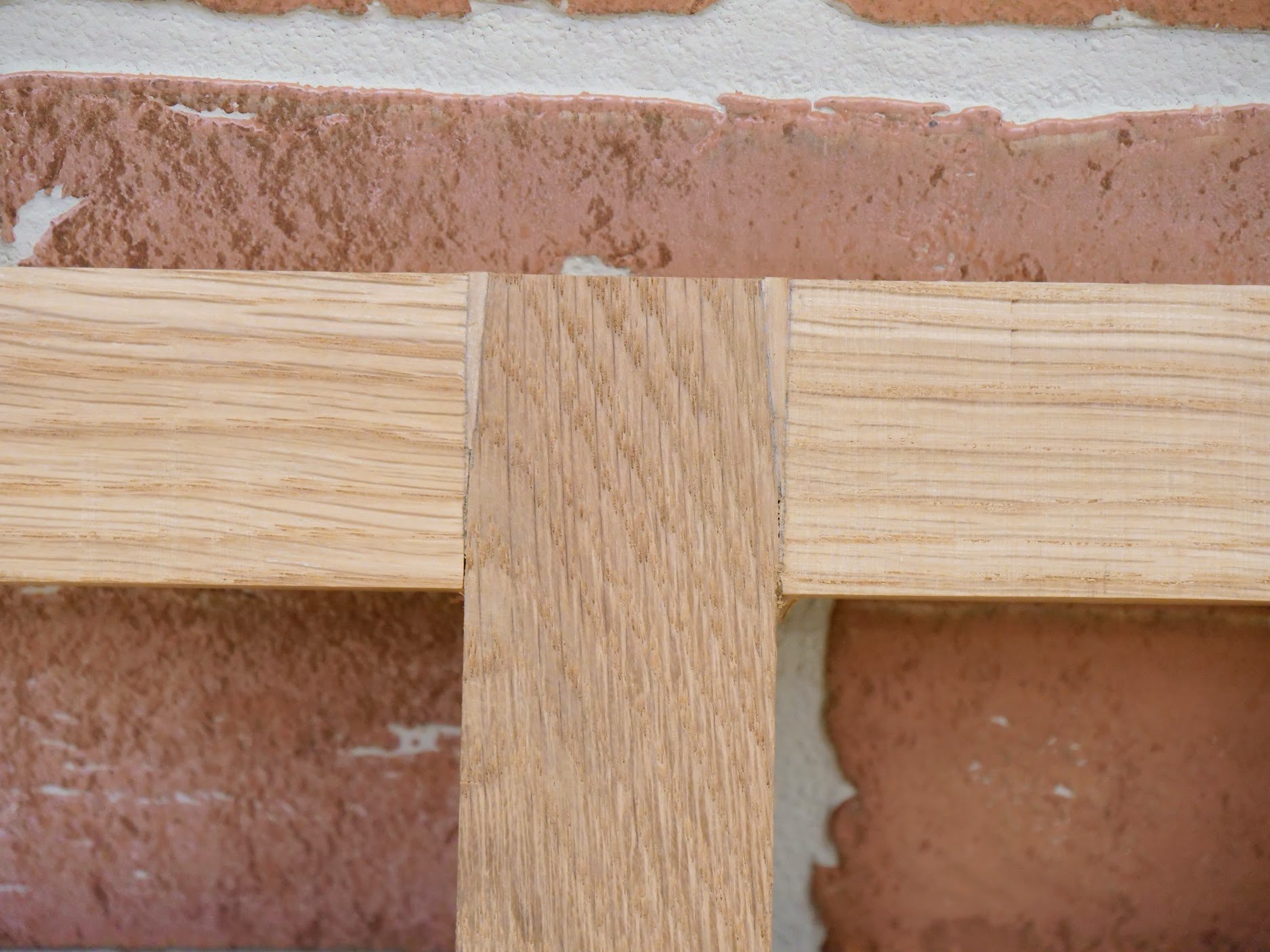
And then there is the ever famed fox wedging of tenons in mortises as shown below.
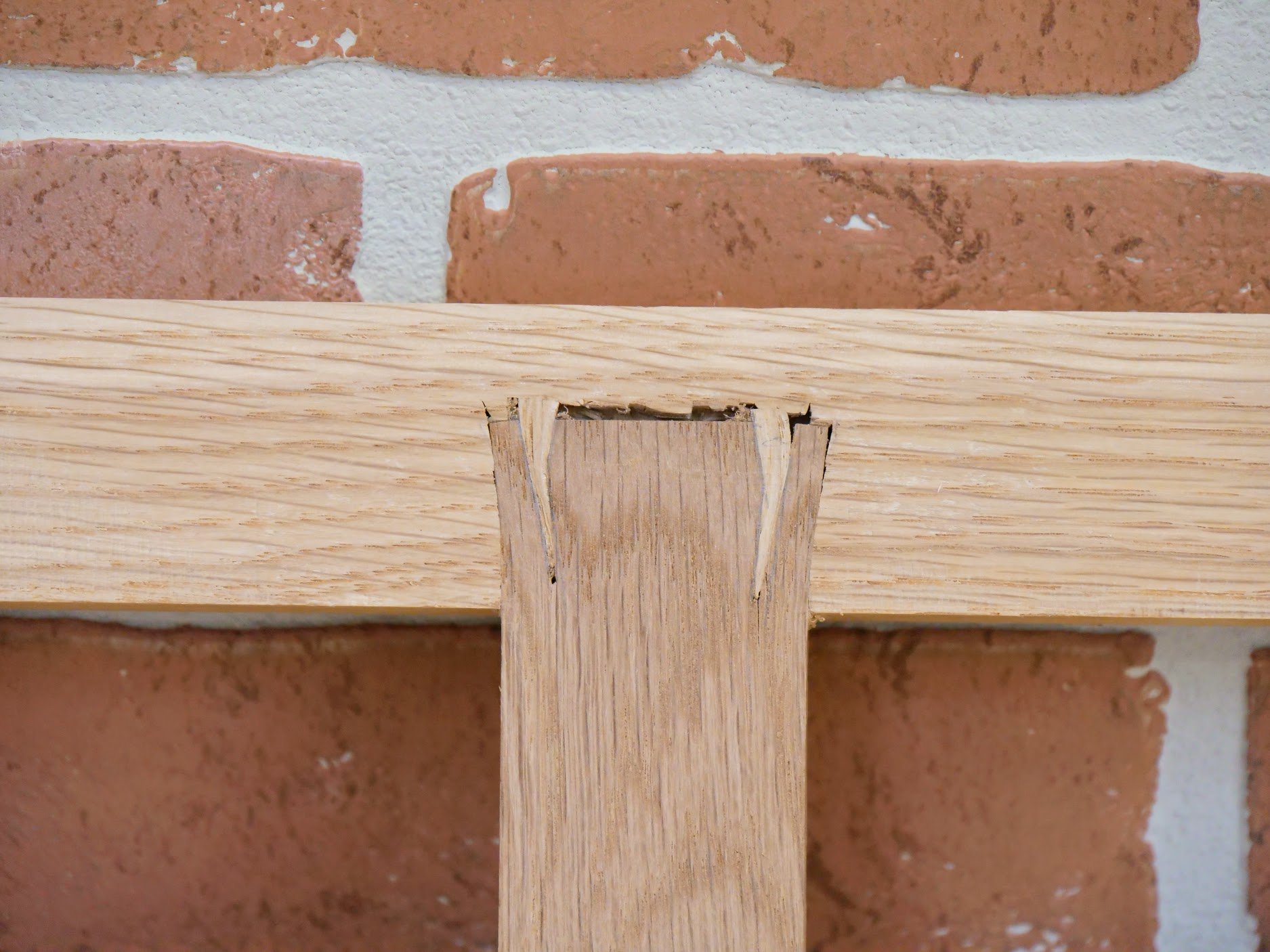
Fox wedging is used inside non-through or stopped mortise and tenon joints. In this case the wedges must be precisely cut so that the kerf length in the tenon is slightly longer than the length of the wedge. That way the wedge is seated when pressure is applied via hammer blows or clamping pressure. Often the mortise ends are left square but, as can be seen in this joint, the opening out of the mortise facilitates the wedges and the tenon element of the joint becomes dovetailed and inextricable.
Comments ()