Rebate Plane No 2—Bullnose Plane Part II
Setting the bullnose plane
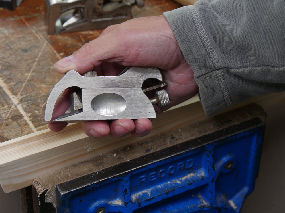
The # 90 bullnose plane is simple enough to use and setting is simple too. The plane can be used in one of two ways, which I have already mentioned in the first section on the bullnose plane. One is where we use the plane fully assembled and then the other is with the top section removed to work like a chisel plane for flush-cutting or finishing that last part of the rebate when it bumps up against an end wall. This takes a little explaining.
As with all planes, the blade protruding through the mouth of the sole means the fore and aft part of the plane sole. Pushing the plane forward from its pivot point on the blade edge engages the blade into the wood. The fore and aft are now engaged with the woods surface. As the surface of the wood is removed by the cutting iron, what’s in front of the blade retains its height but what’s after the plane lowers the mid section between the mouth sides of the plane but there is an element of lowering that happens to the height of the new surface cut by the blade. Compressions are taking place to certain narrow aspects of the surface. This occurs once the plane exhausts its rear support length. The thinner the shaving the less noticeable the difference. Shavings can be around a thousandth so indiscernible by fingertips generally. Rebate planes have no side element either side of the plane blade so pushing the bullnose forward automatically drops the plane the depth of its cut; light shavings only a little and thick shavings a lot. This is indeed a little different than say the bench plane like the #4 and all of the others in the bench plane series. For rebate work using the bullnose the width of the cut is usually narrow, 1/2” or less. When we remove the fore part of the 90 bullnose by unscrewing the setscrew, if the blade is still in the protruding position, where the blade goes past the sole, the blade will penetrate the wood too deeply. In this mode the blade should be flush with the sole as the wood to be removed will be either in the form of a short step at the end of a rebate and above the surface of the main body of wood or material is protruding past the surface of the main body of wood and needs trimming off as say in the case of the top of a plug or a narrow inlay, something like that.
It is well worth noting that the physics of the plane in the cut changes when we remove or install the top section of the plane to create the ‘toe’. The shaving itself develops a tight curl as shown here. To create a shaving is very different than with the plane fully assembled because you must basically incline the planes sole to indeed take any kind of contours shaving and so the shaving is tapered from the start point and must increase in width as the plane is pushed into the wood. This inclining of the plane body and thereby the sole in its relation to the wood is much less controllable so this removal of the top section of the plane is the scarcity rather than normal because the functionality of the plane is severely limited. Basically the two places this adaptation results in functionality is for finishing off a stopped rebate and for the removal of protruding material above an existing and finished level.
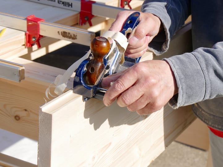
Below shows how very different the resultant shaving is with the top section of the plane in place.
That settled, I took two shavings for comparison to show that physical dynamics do indeed take place which drastically affect the plane. The shaving on the left is without the planes top section in place to create the toe. On the right we have the toe in place and return to a very controllable plane giving exquisite control and exquisite work.

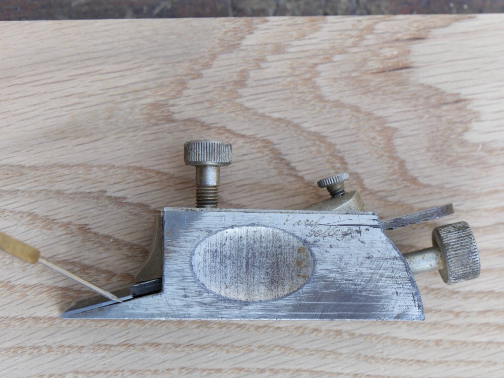
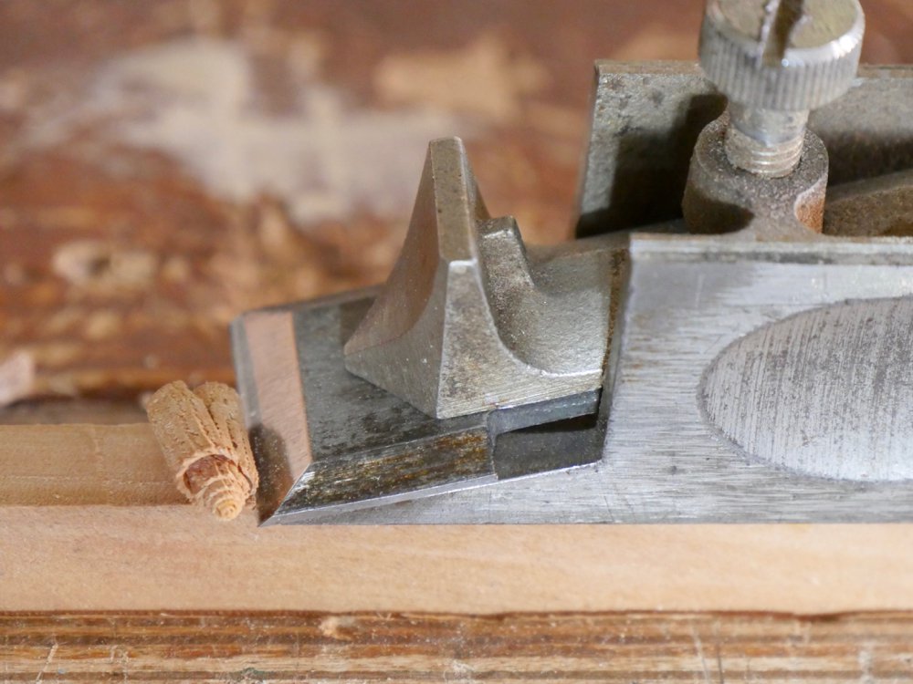
Looking inside the plane body we see the blade and the part that Stanley calls the lever. I have called it both the lever cap and the lever. This component presses against a cross member in the inside recesses of the body casting of the plane to use this as a fulcrum point along the lever cap. Through this we are able to apply pressure to behind the blade and this eliminates or at least minimises chatter at the cutting edge of the cutting iron. So, hopefully, the two following images show the gap open at the point showing between the blade and the bed of the plane. This first image shows the gap expanded before any pressure is applied via the lever.
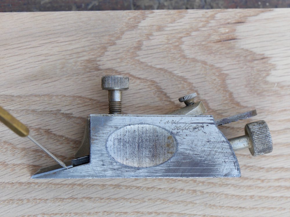
When we apply pressure to the lever cap via the small setscrew set into the top end of the lever cap we transfer pressure to the fore end of the lever cap. This also tensions the blade which does not sit tight to the bed wholly along the blade’s flat face but bends the blade and closes a gap between the bed and the plane iron (see image above). The more pressure you apply the more closed the gap, but you do run the risk of cracking the lever cap if you apply too much torque so be sensitive.
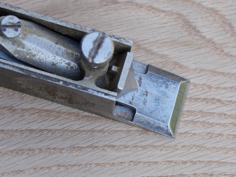
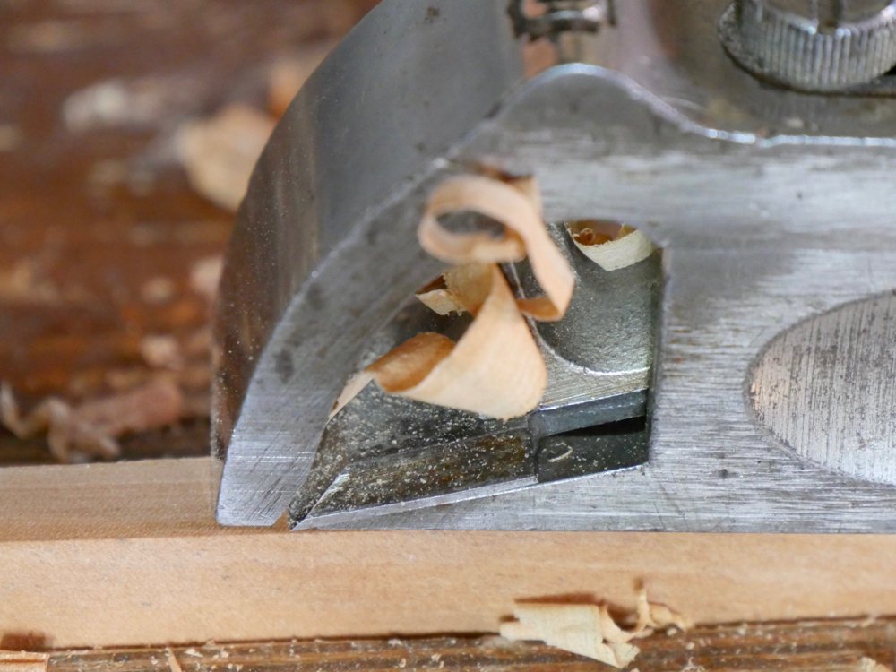
It is worth noting that you can also adjust the distance you set the lever to the fore end of the cutting iron. The reason we vary any distance here is for times when we want to hog off heavy cuts, which in rebating we generally always do to get depth. The above image shows the maximum distance between the lever and the cutting edge. Remember that once you have established say a 1/8” deep wall with a #78 you can switch to #90 bullnose plane and use it freehand to get the rebate down in record time using the plane with a heavy set. Some will say why do that when you can do that with the #78 but the reason is the #78 tends to clog more readily than the #90 and you just poke your finger through on the #90 to express any closing whereas with the #78 it is a little more awkward.
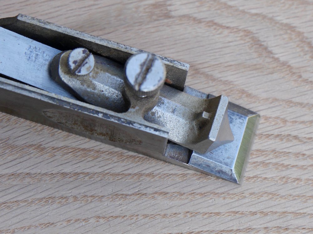
The image above shows the closest setting of the lever to the cutting edge.
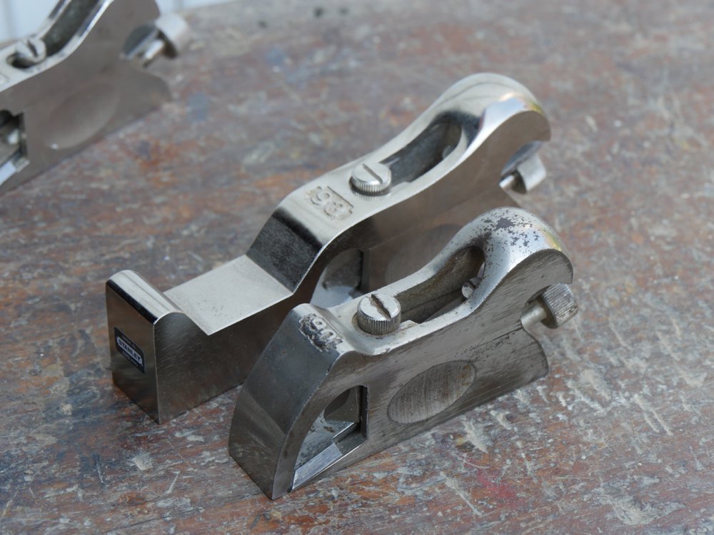

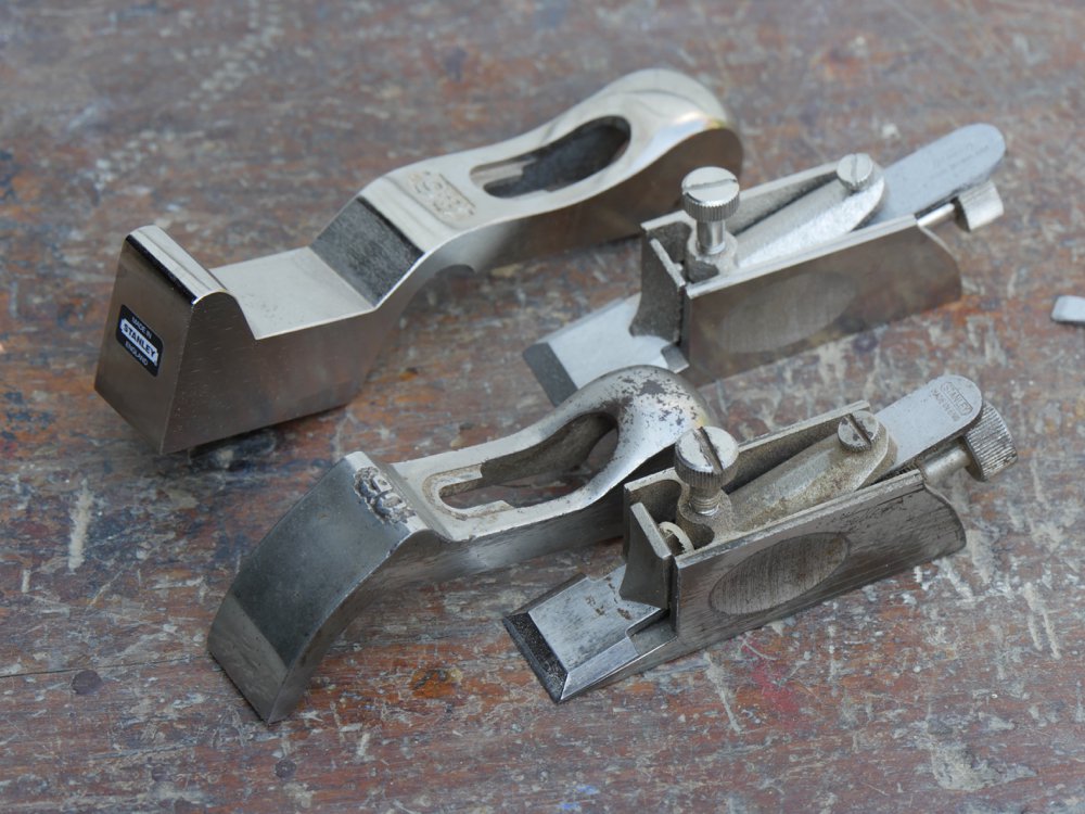
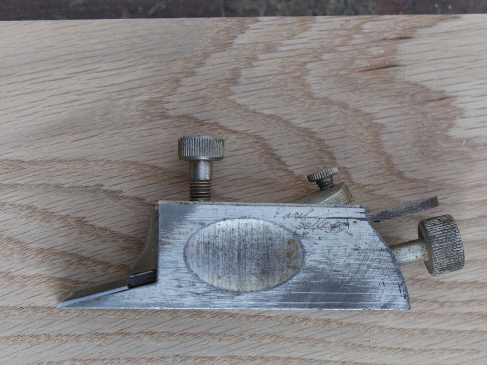
If you happen to own a #90 bullnose and find #93 shoulder rebate plane top section you can use this on the #90 and you have shoulder plane for little less money. These two planes have interchangeable top pieces. The only issue you might find is the castings may be slightly different between the years of casting but I have always found that they do fit just fine.
The top section of the plane is recessed to fit over two milled recesses each side of the plane. This creates a sliding ability which we use to adjust the throat opening of the plane. By slackening the knurled setscrew we can loosen the toe section, position it in relation to the blade and retighten the setscrew.
The adjustment mechanism
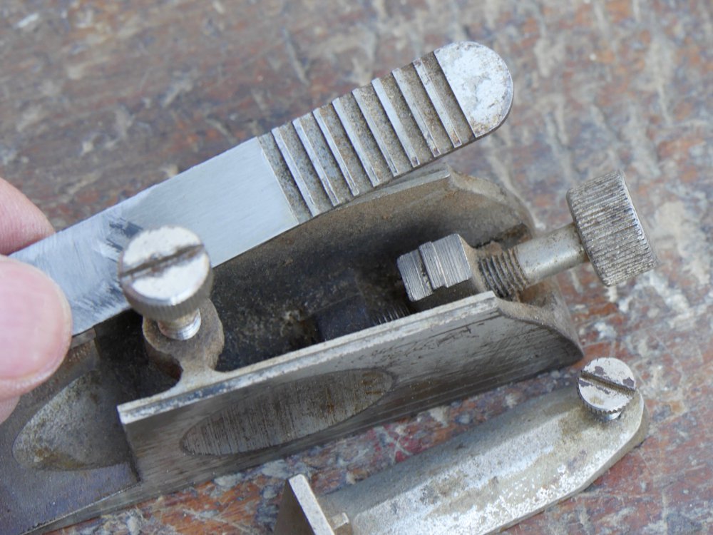

The adjustment of the plane comprises a screw-threaded rod called the cutter adjusting screw, which as parallel aspects to stepped, threaded stem that allow a moving block to move along the threaded stem and so set the plane to a particular depth as needed. In the top of the block casting is rectangular section protruding from the block that engages in grooves milled into the underside of the cutting iron. This provides ultimately variable positioning for the blade as the blade is shortened through decades of sharpening. My plane still has the original iron after 50 years of use and looks as though it has another 100 years life left in it at the moment of writing.
Here you can see a gap directly at the leading point of the lever cap. Whereas shaving can enter this gap it is the rarity and not the norm because the shavings actually rise away from the bevel of the cutting iron well before touching the lever cap. The lever cap has two scallops either side of the fore edge. This diverts the shavings from whichever side of the plane the plane is removing the shaving. I think as well as calling the component a lever cap we should also call it a diverter too.

Comments ()