How to Build a Workbench – Leg Frame Joinery (part4)
NOTE:Just so you know, this is an older workbench series. Paul has a newer Workbench series. If you are interested in the updated version of Paul’s workbench please click the button down below. This page links to a cutting list, tools list, FAQS and much more.
Click here to go to the workbench page
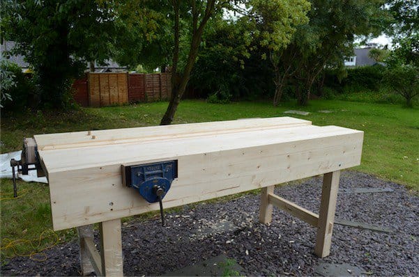
Making the leg frames
Mortising the legs
It’s time to form mortise holes in the legs. If you plan on having a tail vise, as I do, the leg frame assemblies will be slightly different one to the other. If no tail vise then all of the legs are laid out the same and so first of all I will assume that that is the case.


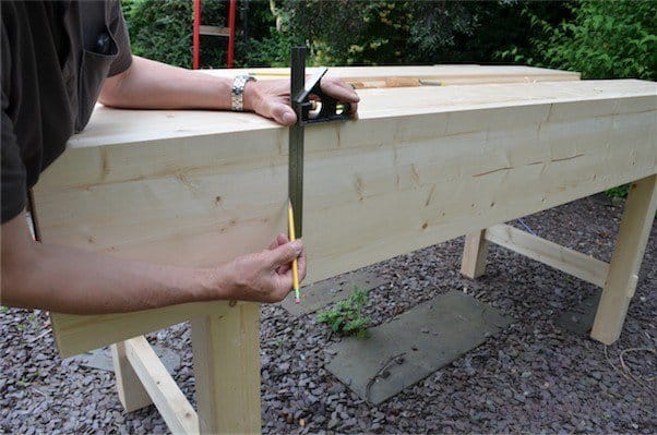
First, with all of my legs cut exactly to length, I measure up from the bottom of the leg 9” and make a mark. I place the pair of legs together, flush the ends and square the line across both legs.

I place the cross-rail on this line and above it. This establishes the mortise width the line. I trace the position across both legs with the pencil.

For the top rail mortise holes I place the top rail flush with the top edge of the legs and mark the width the pencil.

I remove the rail and then measure down from the top of the leg 1”. This is usually the width of the blade of the square: There will be a haunch at the top of the leg. This is a form of step down on the tenon that allows the full encasement of the tenon while ensuring that the tenon rail is fully held within the mortised recess by a step-down. This will be made simple shortly. I now square these lines onto the opposite faces of the legs using the square, simple.

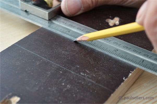
To delineate the exact width of the mortise and position it in the centre of the leg, I deduct the width of the chisel, ½”, from the width of my front leg, which measures 4”, so my remaining measurement is 3 ½”. By splitting this amount, my mortise hole is positioned centrally in the leg. Typically, we use a mortise gauge for this, I cannot assume that you have one and therefore I want to show an alternative possibility first.


In this case I am using my combination square set to 1 ¾”. I could just as easily use a rule and run the parallel line with my finger setting the distance for the pencil line. Here I am showing both the marking with the combination square and then with the mortise gauge.

To set the mortise gauge, I first set the distance of the pin points (not the base) to the width of the chisel and then set the distance of the stock of the gauge to the first pin, centred in the leg width.

Now I can run parallel lines easily along the length between the lines.
Comments ()